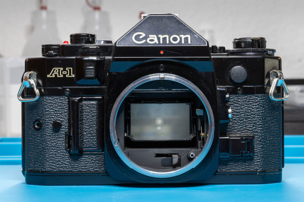
Disclaimer: The information I present in this post is based on the official service manual and renowned repair articles but also reflects experiments I performed. The information may be incomplete and might even contain errors. Consider that I am just a self-taught hobbyist, not a trained professional. Also, consider that any attempt to disassemble and repair a camera carries a certain risk to worsen its condition or to even breaking it completely.
The release magnet MG2 of the Canon A-1 is an essential part of its shutter release mechanism. If it gets faulty, the camera will no longer work properly. In this post, I explain the functionality of the magnet and describe typical errors and how to identify and solve them.
To my knowledge, the release magnet MG2 is used in all camera models of the Canon A-series (A-1, AE-1, AE-1 Program, AL-1, AT-1, and AV-1). However, I cannot guarantee that all physical properties of the magnet are identical across the models. Also, the details of its control circuit might vary.
The Purpose of the Magnet
The Canon A-1 uses a focal plan shutter with two cloth curtains that travel horizontally. The shutter release button works purely electrically. When you press it, an electric contact is closed that starts the “take a picture” process. After a couple of preparatory steps, like battery check and exposure calculation, it is time to also start the mechanical part of the process. This is the purpose of the release magnet MG2. The magnet is activated and releases a spring-loaded armature that moves a lever in the mirror box. In turn, this lever initiates the flipping up of the mirror and (if the mirror is flipped up completely) the release of the first shutter curtain. Therefore, MG2 (sometimes also spelled “MG-2”) is called “release magnet”, “mirror release magnet”, or “first curtain magnet”.
The Position of the Magnet
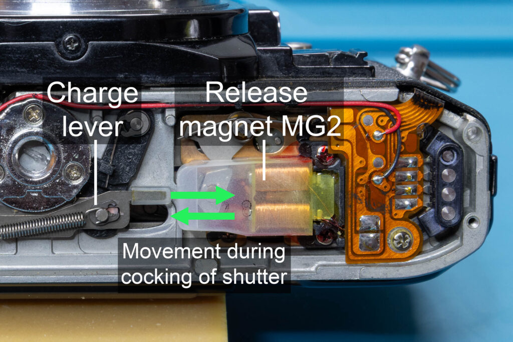
The magnet is located at the bottom of the camera, on the rewind side. To reach it, you have to remove the bottom cover of the camera (see this post on how this is done).
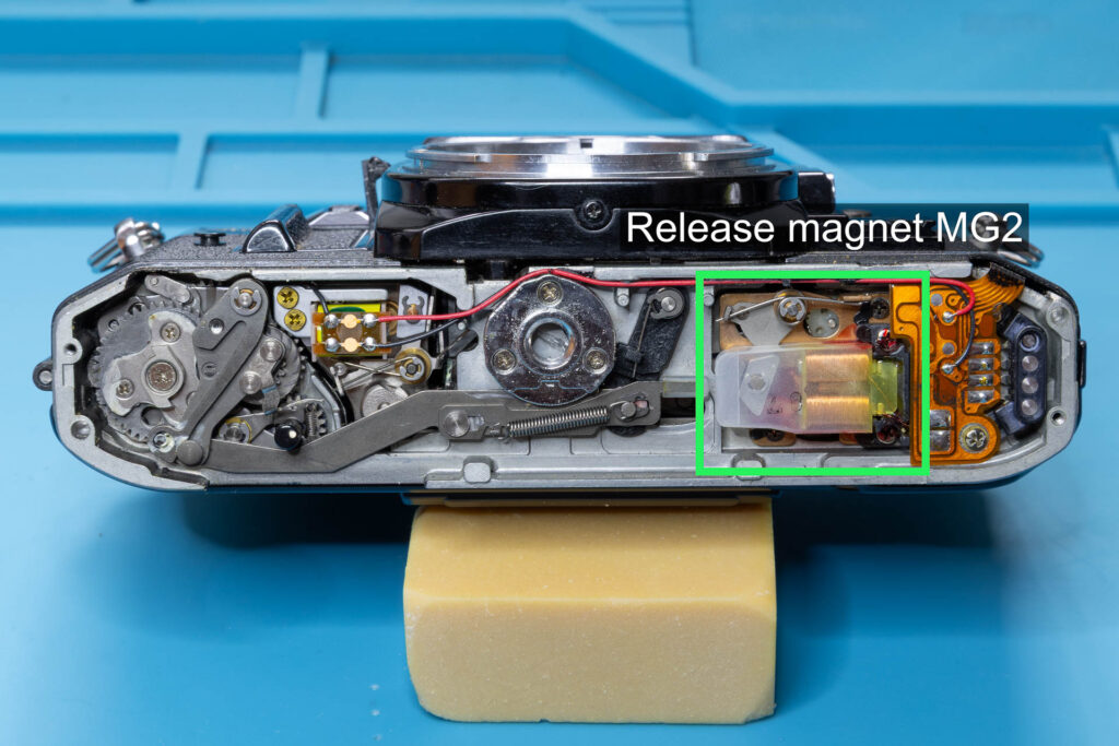
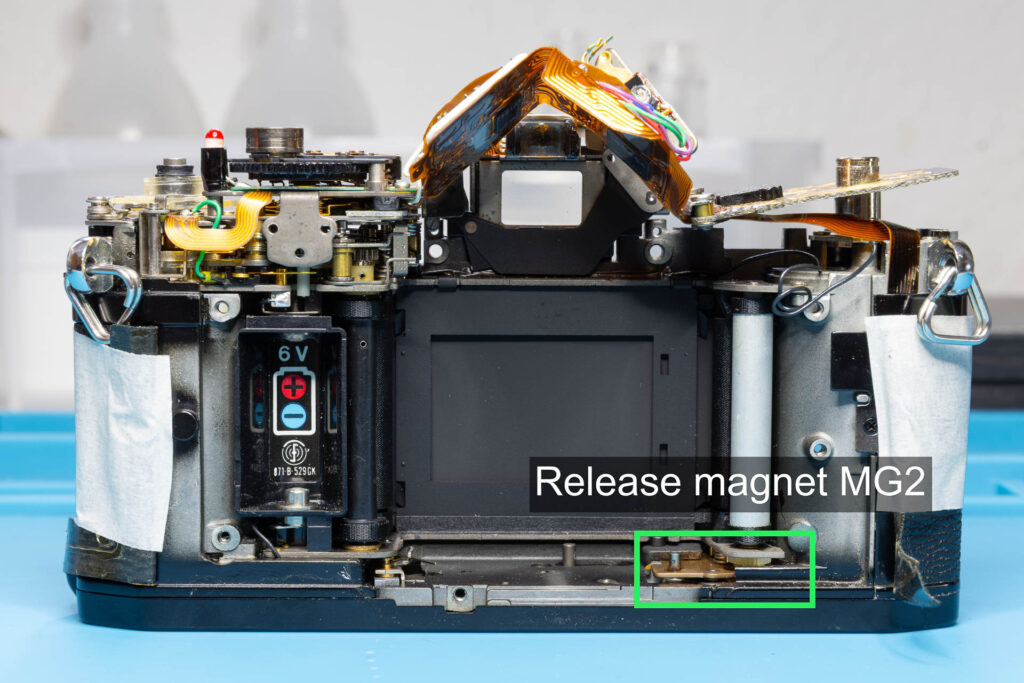
The Components of the Magnet
The release magnet (to be precise, the release magnet assembly) consists of the following main parts:
- the actual magnet
- the armature lever
- the armature
- a plastic cover to protect the magnet
- a base plate on which the magnet and the armature lever are mounted
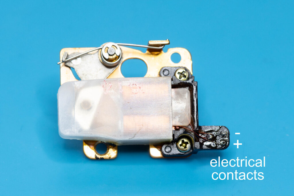
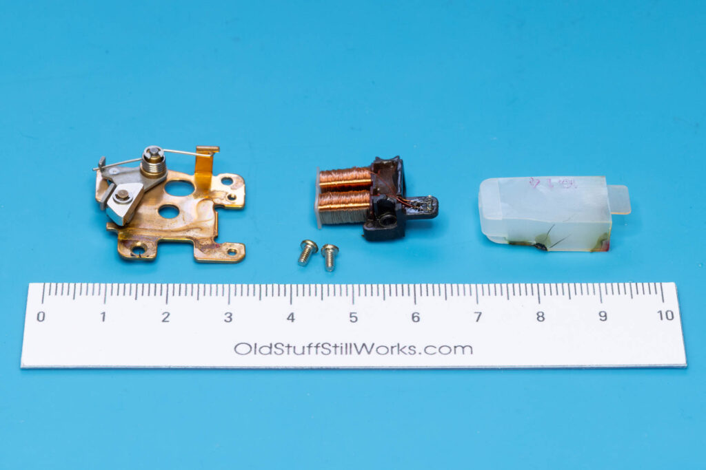
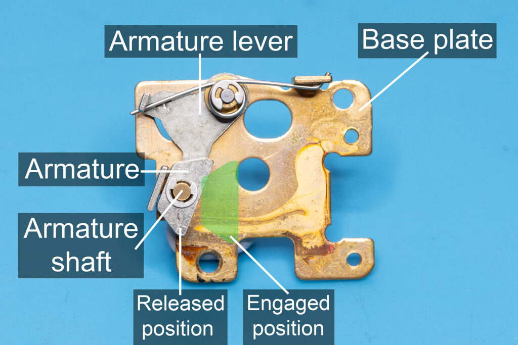
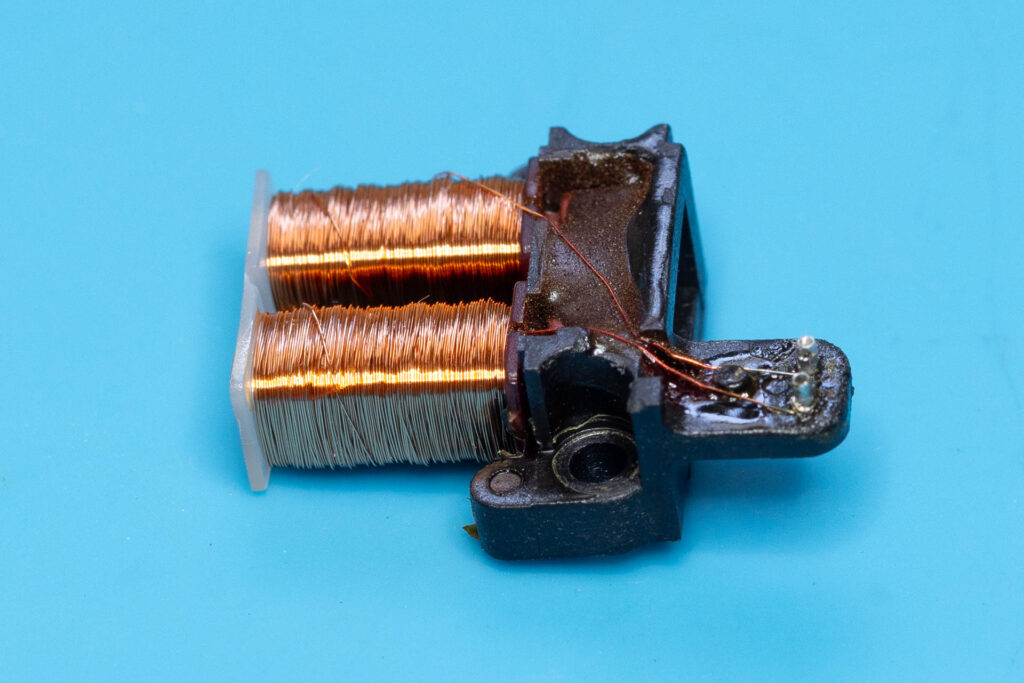
The actual magnet is a “combination” magnet (sometimes also called “hybrid” magnet or “HMER” = Holding Magnet Electric Release) since it consists of electromagnets (here: solenoids) that have permanent magnets as core. If no current flows through the solenoids, the force of the permanent magnets is sufficient to keep the spring-loaded armature engaged. If current flows through the solenoids, they produce a magnetic field that has the opposite direction of the magnetic field produced by the permanent magnets. As a result, the overall magnetic field acting on the armature is weakened and the armature is released.
I carried out some measurements with a DIY magnetometer that I built recently. If no current flows, the magnetic flux density is about 120G at the core of the lower solenoid and about -100G at the core of the upper solenoid. Measurements where taken with the base plate and armature of MG2 removed. Take this values with a grain of salt since I only tested two copies of MG2 and my magnetometer is not calibrated.
In the repair sources available to me, varying, but similar values are given for the total resistance of both solenoids (that are connected in series), ranging from 90 ohm to 97 ohm.
For the three copies of MG2 I tested, the resistance was between 92 ohm and 94 ohm.
The armature lever is a pivoted, spring-loaded lever mounted to the base plate. A ferromagnetic armature (“keeper”) sits on a shaft at the longer side of the lever. On this shaft, the armature can turn slightly (not more than 1°-2° in both directions). When engaged, the armature is pressed against both cores by their magnetic field. When released, the lever rotates about 15°-20° in clockwise direction. A post on the underside of the lever moves about 1.5mm towards the front of the camera and strikes the main-release lever of the mirror box.
When you use the film advance lever of the camera to cock its shutter, the charge lever pushes the armature back against the cores of the release magnet. The magnetic field of these permanent magnets can keep the armature engaged for an almost unlimited time, even if you switch off the camera or remove the battery.
The Control Circuit
As explained above, the armature is released when sufficient current flows through the solenoids of the MG2 magnet.
In my experiments, it was sufficient to apply about 1.2V-1.5V DC (with correct polarity!) to the electrical contacts of the magnet to release the armature. This results in a current of about 15mA.
To understand when and how the release voltage is applied to the magnet, have a look at the following (simplified) schematic:
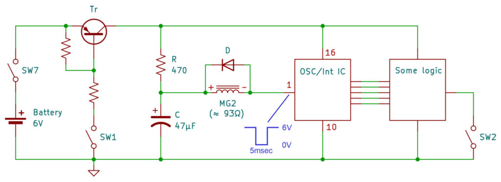
On the left side of the schematic, you see the power supply of the camera. It mainly consists of a 6V battery, the main on/off switch SW7 (‘A’ = on, ‘L’ = off), the metering switch SW1 (shutter release button half-pressed), and a PNP transistor acting as the electronic power switch of the camera. The circuit of the camera is only powered (Vcc ≈ 6V DC) when (a) switch SW7 is turned on and (b) switch SW1 (or another switch not relevant here) is pressed. When this happens, the capacitor (47 µF) is charged via the resistor (470 ohm*) to Vcc. This takes less than 100msec.
(* There seem to be two variants of the charging resistor. The similar circuit of the Canon AE-1 as well as those of early variants of the Canon A-1 seem to use a 2.2 kiloohm resistor while later variants of the A-1 use a 470 ohm resistor. The copies of the A-1 I checked all had the “later” 470 ohm resistor. The only relevant difference between both variants is that the 2.2 kiloohm resistor charges the capacitor a bit slower than the 470 ohm resistor.)
The positive (‘+’) terminal of the release magnet is connected to the anode (positive terminal) of the capacitor, the negative (‘-‘) terminal to Pin 1 of the OSC/Interface chip. As long as switch SW2 (shutter release button pressed completely) is not pressed, both connection points have a potential of ~Vcc. Therefore, no current flows through MG2 and its armature is not released. When switch SW2 is pressed, the “take a picture” process starts. After a couple of preparatory steps, like battery check and exposure calculation, Pin 1 of the OSC/Interface chip drops from ~Vcc to 0V for about 5msec. In other words: The negative terminal of MG2 is connected to ground and, thus, MG2 is connected in parallel with the capacitor. Since the capacitor is charged, there is a potential of ~Vcc on the positive terminal and of 0V on the negative terminal of MG2. Therefore, the capacitor is discharged through the solenoids of MG2. During this process, the solenoids produce a magnetic field that is opposite to the magnetic field of their cores. When the overall magnetic field has dropped to a certain flux density, the spring-loaded armature is released and, in turn, releases mirror and first shutter curtain. After about 5msec, Pin 1 of the OSC/Interface chip jumps back to ~Vcc, the capacitor is recharged and the current flow through MG2 stops.
The diode connected in parallel with MG2 has no release-specific functionality. It is just a flyback diode as commonly used for electromagnets to protect the circuit from negative voltage spikes.
The Time Course of the Magnetic Field
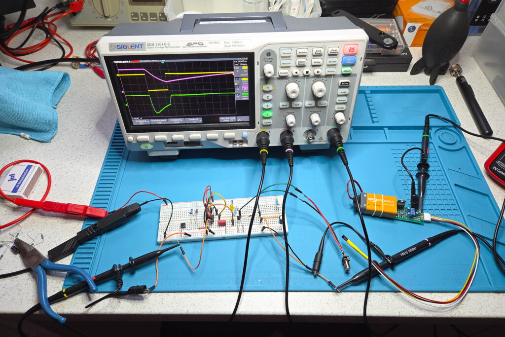
To illustrate the time course of the total magnetic field of MG2 during the release process, I rebuild the essential circuit on a breadboard for easier accessibility. The schematic of this test circuit looks like this:
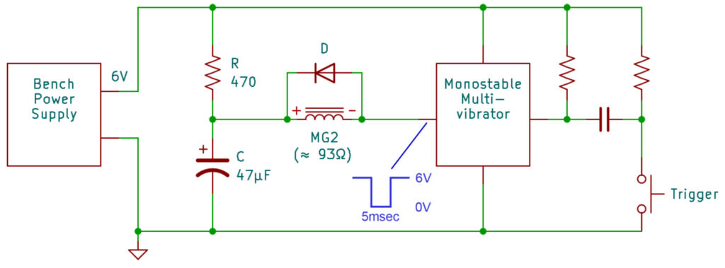
In my test circuit, I replaced the battery-based power supply of the camera by a bench power supply, set to 6V DC. I also replaced the OSC/Interface chip (and everything behind it) by a simple monostable multivibrator. Whenever the trigger button is pressed, the output of the multivibrator drops from 6V to 0V for about 5msec. I removed the base plate, armature lever, and armature from MG2 to measure the magnetic flux density directly at its cores.
For the measurements, I used three channels of my digital oscilloscope (Siglent SDS 1104-X) that captured the following information:
- Channel 1 (yellow):
The output of the multivibrator with the 5msec voltage drop, simulating the release signal of the OSC/Interface chip. - Channel 2 (purple):
The voltage across the capacitor. - Channel 3 (green):
The magnetic flux density at the lower core of MG2. Measured with my DIY magnetometer.
This is the main measurement result (horizontal scale: 2msec/div):
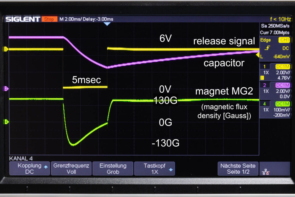
Everything starts with the release signal (yellow curve) dropping to 0V. By this, magnet MG2 is connected in parallel with the charged capacitor that starts to discharge through MG2 (purple curve). When the discharge starts, the magnetic flux density at MG2 drops from 130G down to 0G (magnet field disappears) within just 0.2-0.3msec (green curve). Sometime within these first 0.2-0.3msec, the armature should be released due to the weakened magnetic field. After the magnetic field disappeared (0G), it returns immediately with opposite direction and increasing magnetic flux density. This means that the magnetic field produced by the solenoids overpowers the magnetic field of their cores. After reaching about -130G after 2msec, the magnetic flux density starts to decrease due to the decreasing charge of the capacitor. By the way: It’s only a coincidence that both extrema, 130G and -130G, have the same absolute value. At the end of the 5msec drop of the release signal, the capacitor has lost about 60% of its charge and the magnet field disappeared again (0G). After the release signal has jumped back to 6V (MG2 no longer in parallel with capacitor), the capacitor starts to charging again and the magnetic field of MG2 returns to the flux density of its quiescent state (about 130G) very fast.
Possible Errors of the Shutter Release
Besides incorrect exposure times and shutter capping, the most common shutter-related errors are:
- You cock the shutter using the film advance lever but at the end of the stroke the shutter releases automatically.
- The cocked shutter is not released when you press the shutter release button completely.
In this post, I will only consider causes of these errors that are directly or, at least, closely related to release magnet MG2. Identifying these causes requires the removal of the bottom cover of the camera, as described in this post. You will also need a multimeter that can measure voltage and resistance.
For the symptom that occurs with your camera, follow the checks and repair suggestions described below in the specified order. If a check does not determine the cause of the error or the proposed repair does not help, continue with the next one. If none of these work, the error is not related to release magnet MG2 and you have to consult the service manual for alternattive checks and repairs.
Shutter Releases Automatically
Cock the shutter while observing MG2 and the charge lever that pushes the armature against the cores. If the armature is not kept by the cores after the charge lever retracts, there is a problem with MG2.
Cause 1: Solenoid Cores or Armature Are Dirty/Oily
For the solenoid cores to keep the armature engaged, the armature has to lay flat on both cores without any gaps. If the cores and/or the armature are dirty or oily, this may create a gap large enough to prevent the armature from engaging.
Carefully remove the protective cover of MG2 and clean the surfaces of the cores and the armature with isopropyl alcohol (IPA).
Cause 2: Armature Is Stuck On Its Shaft
The armature is designed to turn slightly on its shaft (not more than 1°-2° in both directions). This ensures that the armature always lays flat on both cores. If the armature got stuck on its shaft (due to corrosion or other factors), it might only touch one core while there is still a gap between the armature and the other core.
Carefully remove the protective cover of MG2 and use tweezers to check if you can turn the armature slightly to the left and right. If it is stuck, remove the armature from the shaft and clean both with isopropyl alcohol (IPA). If it is still stuck, you have to replace MG2.
Cause 3: Solenoid Cores Are Too Weak
The two cores of the solenoids of MG2 are permanent magnets. They are responsible for keeping the armature engaged. Under adverse conditions, the magnetic field of a permanent magnet might get weaker over time. Such conditions are, for example, heat/cold, physical shock/vibrations, and external magnetic fields. If the magnetic field of the solenoid cores is weakened beyond a certain point, they cannot keep the armature engaged, it will just jump back to its released position.
You have to replace* MG2.
(* It seems that some people have tried to “revitalize” the cores by applying a strong magnetic field. Since I have no experience with this procedure, I cannot comment on its effectivity. However, if I come across a MG2 with this error I will try this procedure and report the results here.)
Shutter Does Not Release
After cocking the shutter, try to release it by pressing the shutter release button. If this does not work, check the usual suspects first (Camera switched on? Battery has sufficient charge?). If these are OK, check if the armature of MG2 is released when you press the shutter release button. If this is not the case, there might be a problem with MG2.
(If the armature is released there is probably a problem in the mirror box. In this case, see the service manual for repair advice. This post described how to remove the mirror box from the camera chassis.)
Open Circuit of the Solenoid Coils
The wire of which the solenoid coils are made of is very thin. It can break due to thermal, mechanical, or electrical stress. If this happens, MG2 is unable to release its armature since the solenoids cannot produce a magnetic field.
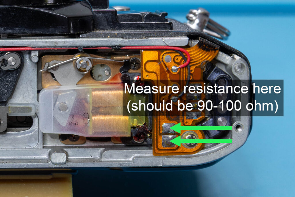
Measure the resistance of the coils at the terminals of MG2. It should be in the range of 90-100 ohm. If you measure an open circuit or a resistance that is far outside the specifications, you have to replace MG2.
Armature is Stuck to the Cores
Check if you can release the armature mechanically by pushing the armature lever towards the front of the camera (for example, using a small screwdriver). Only a small initial force should be needed to do this. If the armature lever does not move or only when using a higher force there might be dirt or corrosion on the post on which the lever turns. Remove the armature lever and try to clean the post. Also, clean the surfaces of the cores and the armature with isopropyl alcohol (IPA). If this does not help, you have to replace MG2.

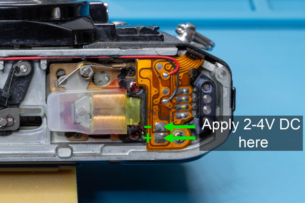
Using an external power supply, apply a voltage of 2-4V DC to the terminals of MG2 (positive to the lower terminal, negative to the upper terminal). If the armature does not release, it might got magnetized, increasing the attraction between the armature and the solenoid cores. Remove MG2 from the camera and try to demagnetize the armature. You should only try this after you have removed the actual magnet from the base plate of MG2! If this does not help, you have to replace MG2.
Faulty Capacitor
To release the armature, a capacitor (47 µF) is discharged through MG2. If the capacitor is faulty and can no longer hold the necesary charge, the armature will not be released.
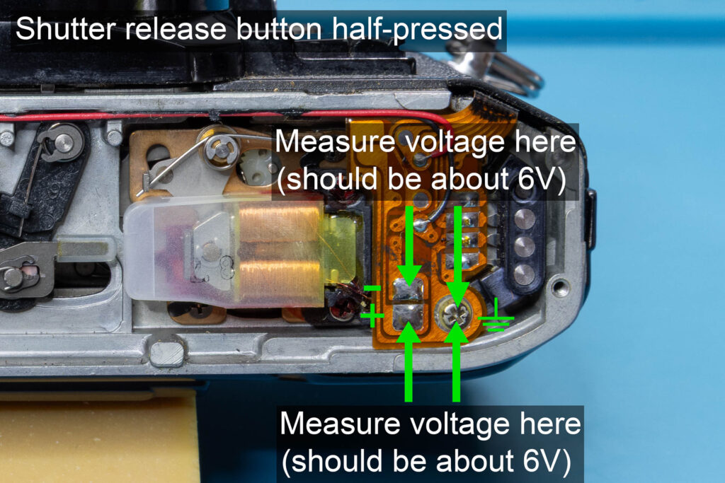
Half-press the shutter release button and measure the voltages at the lower and upper terminal of MG2 against ground. As ground, you can use the screw to the right of the lower terminal. At both terminals, you should measure about the battery voltage (~6V DC). If you measure 0V at the upper (negative) terminal, there might be a problem with the OSC/Interface chip or the flexible board leading to it. In this case, see the service manual for further repair advice. If you measure 0V at the lower (positive) terminal, the capacitor seems to have a short circuit and needs to be replaced.
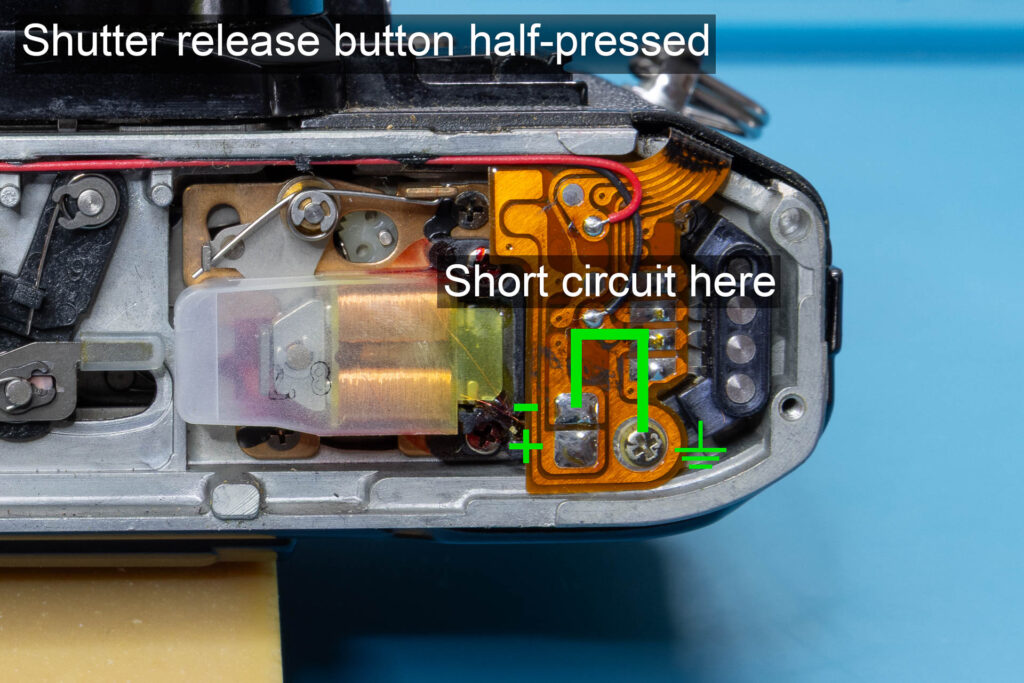
Half-press the shutter release button and short circuit the upper (negative) terminal of MG2 against ground. For the short circuit, you can, for example, just use tweezers. If the armature is not released, the capacitance of the capacitor is either too low or it has an open circuit and needs to be replaced. If the armature releases, the capacitor is OK. In this case, see the service manual for further repair advice. For example, you could use an oscilloscope at the upper (negative) terminal of MG2 to check whether you see the 5msec release pulse sent from the OSC/Interface chip.
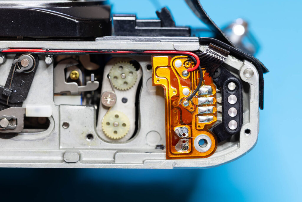
The capacitor is located on the underside of the flexible board to the right of MG2. You will have to remove one screw and desolder both terminals of MG2 and four terminals of the motor-drive connector. Afterwards, you can lift the flexible board. Be careful to no damage or break this board.
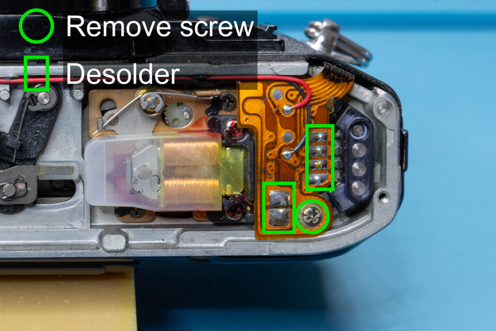
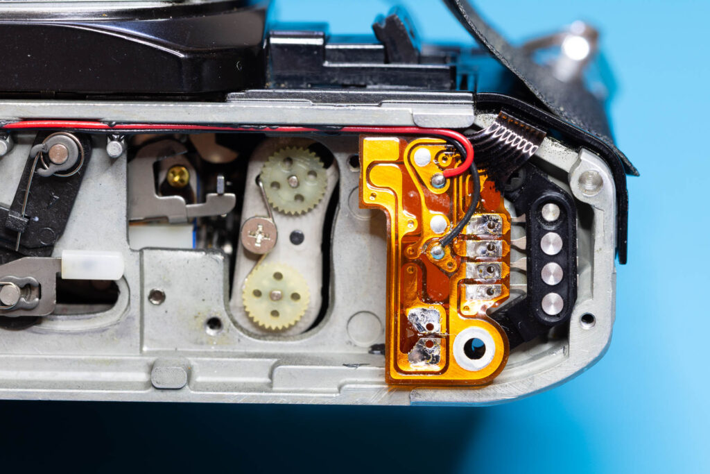
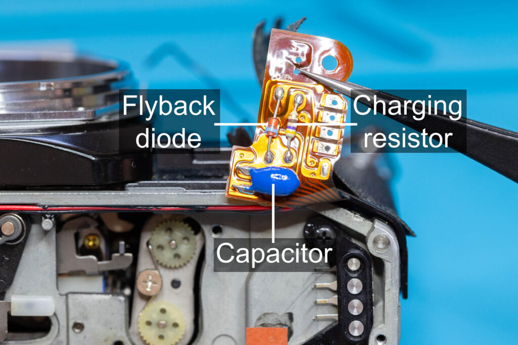
(Contrary to what is shown on the second and third picture above, it is not necessary to remove MG2 before replacing the capacitor.)
Replacement of the Magnet
A faulty release magnet MG2 can be replaced in the following way: First, remove the bottom cover of the camera as described in this post. Then, desolder both terminals of MG2. Afterwards, remove the two screws that attach MG2 to the camera chassis. Then, lift the flexible board slightly and remove MG2 to the left. For this, it might help to also remove the screw to the right of the lower terminal of MG2. Be careful to no damage or break the flexible board. For the installation of the new release magnet, just perform the steps in reverse order.
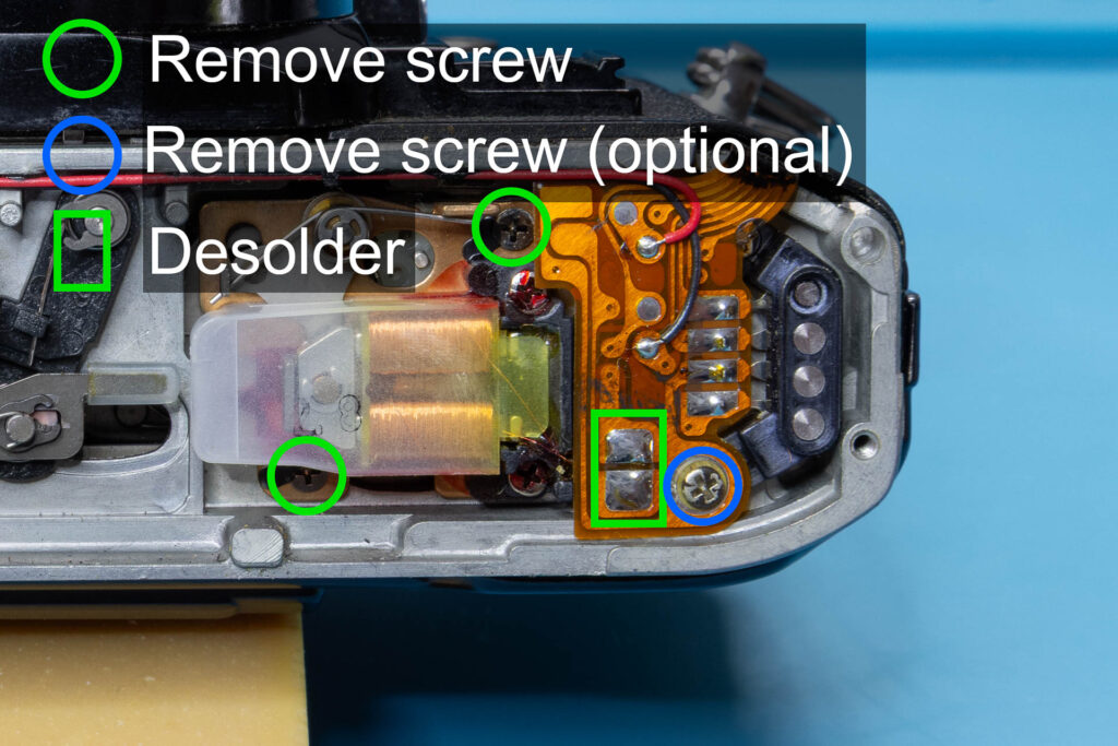
That’s all.