Disclaimer: In this post, I present a project that I finished successfully. However, it is not meant as a detailed construction manual. The description may be incomplete and might even contain errors. Feel free to use it as an inspiration for your own project but scrutinize the information presented here and use your common sense. Build at your own risk!
Some time ago, I found a (seemingly) defective electromagnet in an old camera. The coil was not open but still the electromagnet did not work correctly. I was wondering if, for some reason, the magnetic field produced by the electromagnet was too weak. In such cases, the measuring device of choice is a magnetometer that can measure the strength of magnetic fields (magnetic flux density). You can buy magnetometers but these professional devices are not cheap and a complete overkill for occasional private use. Therefore, I decided to build a simple, inexpensive one by myself.
The credits for the general idea, the basic design, and the selection of the sensor go to K&J Magnetics that published the blueprint of a simple magnetometer in their blog. I have only slightly extended the design in several, smaller points. I will point out these extensions in the text.
The Magnetic Field
A magnetic field is a “physical property of space that quantifies the magnetic influence at a given location” (Wikipedia). It is characterized by two vector fields, the magnetic field strength vector H and the magnetic flux density vector B. In this post, I will only consider the magnetic flux density B since it is the field that causes magnetic forces, magnetic torques, and electromagnetic induction. The SI unit of magnetic flux density is Tesla (symbol: T). However, for “everyday” magnetic fields the older unit Gauss (symbol: G) is more common. 1 Gauss equals 0.0001 Tesla. A magnetometer is a device that measures the magnetic flux density B.
Magnets are objects that create their own magnetic field. In many cases, they can be described (somewhat simplified) as objects with two opposite magnetic poles, a north pole and a south pole. Opposite poles of two magnets attract, means, the north pole of one magnet is attracted to the south pole of the other magnet (and vice versa). By convention, the magnetic flux density of a north-polarity magnetic field (B–) is described by negative values and those of a south-polarity magnetic field (B+) by positive values.
Tip: Some magnets have painted poles, red for the north pole and blue for the south pole. If this marking is missing you can identify the poles of a magnet using a compass. Put the magnet perpendicular to the compass and observe its needle. If the side of the magnet facing the compass attracts the north pole of the needle (often painted in red or marked with letter ‘N’) then this is the south pole of the magnet (and vice versa). If the magnet is very strong don’t put it too close to the compass since the compass might get damaged!
The Hall Sensor
The Hall effect, discovered 1879 by the American physicist Edward Hall, describes the deflection of charged particles moving in an electrical conductor in the presence of a perpendicular magnetic field. This results in a potential difference that can be measured. Nowadays, this is often done using inexpensive, semiconductor-based Hall sensors. One such sensor is the A1302 of UK-based manufacturer Allegro Microsystems. It produces an output voltage proportional to the flux density B of the magnetic field with about 1.3 mV/G sensitivity. It covers a measuring range of about -2,000G … 2,000G. Although already discontinued, you can still buy this sensor for not more than $2-$3. If you cannot find it, you can also use its successor, the A1308. However, ensure that it has the same 1.3mV/G sensitivity or you may need to change part of the circuit described here.
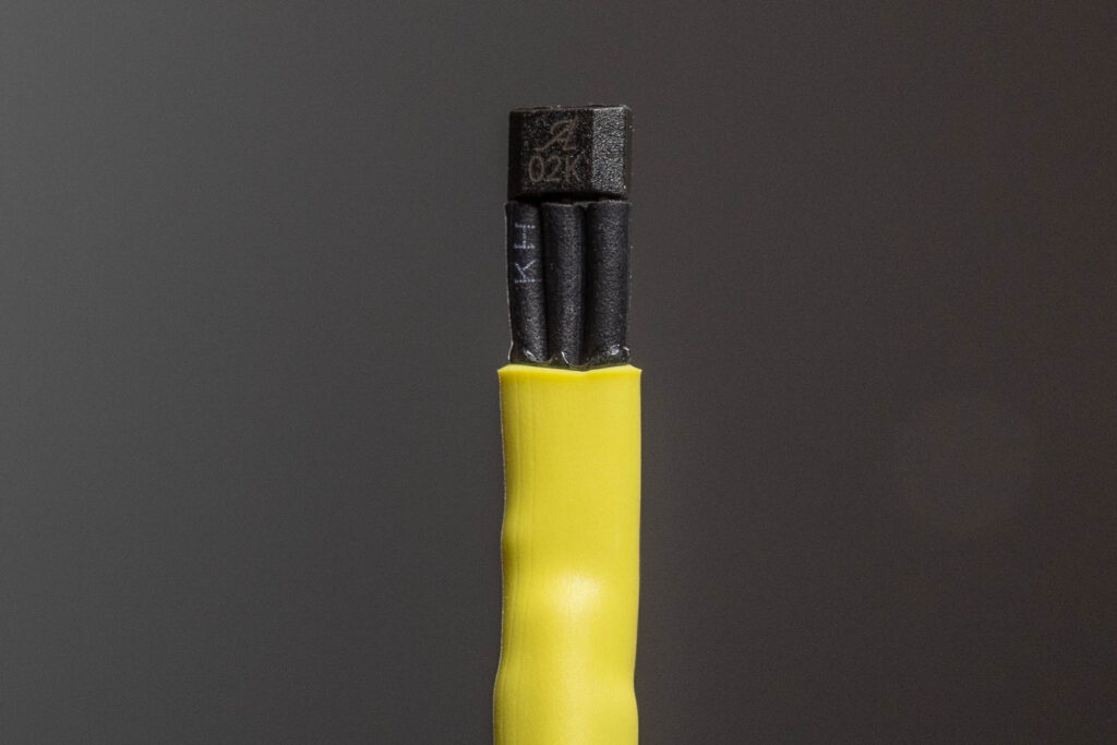
The A1302 is available in two packages, a SOT-one and a SIP-one. We use the SIP-one that looks like a classic, through-hole transistor. The A1302 has only three terminals (pins), one for the supply voltage (Vcc; 4.5V-6.0V), one for ground (GND), and one for the output voltage (Vout; 0.2V-4.7V). In the absence of a magnetic field (quiescent state), Vout is about 1/2 Vcc. Vout gets proportionally higher (for a south-polarity magnetic field B+) or lower (for a north-polarity magnetic field B–) than 1/2 Vcc in the presence of a magnetic field. For example, if you have a classic, rod-shaped permanent magnet and press the sensor against its south pole, Vout may change from 2.5V (1/2 Vcc) to 3.15V. This corresponds to (3.15V-2.5V) / 0.0013V/G = 500G. If you press the sensor against the north pole of the magnet, Vout may change from 2.5V to 1.85V. This corresponds to (1.85V-2.5V) / 0.0013V/G = -500G.
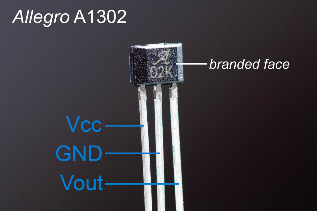
Important: When measuring magnetic fields with this sensor, always align its branded face (the beveled face with the ‘A‘ print) towards the source of the magnetic field. If you want to measure the maximum flux density of the magnetic field, try to minimize the air gap between the magnet and the branded face of the sensor. The reason for using the branded face instead of the opposite, flat face is that the Hall element inside the sensor is closer to the branded face (about 0.5mm). This can make a difference in measured values. Also, the correct identification of south-polarity vs. north-polarity magnetic fields only works when using the branded face of the sensor.
What You Need to Build the Magnetometer
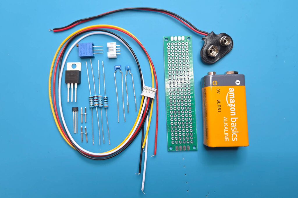
Parts
- small perfboard 8x2cm (28×6 holes, 2.54mm square grid)
- Hall sensor Allegro A1302
- 5V voltage regulator 7805
- ceramic capacitor 100nF
- ceramic capacitor 330nF
- 2x resistor 330 ohm (0.125W is sufficient)
- resistor 12 kiloohm (0.125W is sufficient)
- resistor 39 kiloohm (0.125W is sufficient)
- variable resistor 100 ohm (precision trimmer)
- 4x solder terminals (used as test points)
- JST PH2.0 3-pin socket
- JST PH2.0 3-pin plug with preconfigured, flexible wires
(I used a JST PH2.0 4-pin socket/plug but only because I had them at hand. You can also use three flexible wires and solder them directly to the board and the sensor.) - 9V battery clip with leads
- some small heat-shrinking tubes
- some small wires
- small piece of anti-slip rubber tape
- two small rubber bands
Tools and Materials
- soldering iron
- solder wire and acid-free soldering flux
- pair of tweezers
- small flat-nose pliers
- small cutting pliers
When Using the Magnetometer
- 9V battery
- digital DC voltmeter with 1mV resolution
The Circuit
The circuit used for the magnetometer is quite simple.
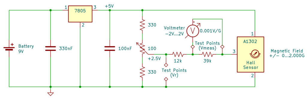
The power supply of the circuit is a 9V battery, reduced to stabilized 5.0V by a 5V voltage regulator (the well-known 7805). This is different from the original design of K&J Magnetics who used the USB port of a computer as power supply. The use of a regulated voltage of a 9V battery makes the magnetometer more portable and eliminates voltage derivations/fluctuations and interference signals induced by the computer.
As explained above, Vout of the Hall sensor is 1/2 Vcc in the absence of a magnetic field (let’s call this “offset” voltage Vout,o). In our circuit, Vcc is 5.0V so that Vout,o is 2.5V. This means, when measuring Vout directly with your voltmeter (Vmeas = Vout) you always have to consider this offset voltage Vout,o of 2.5V. In other words, you would always need to calculate (Vmeas-2.5V) / 0.0013V/G to get the flux density of the magnetic field in Gauss. Since this would be a bit cumbersome, the circuit contains a 2:1 voltage divider consisting of two 330 ohm resistors and a 100 ohm precision trimmer for fine-tuning (the latter also not part of the original design). At the output of the voltage divider, we get a reference voltage Vr = 2.5V (= Vout,o). Now, we can measure voltage Vout of the Hall sensor against this reference voltage instead of against ground so that Vmeas = Vout-Vr = Vout-2.5V. This simplifies the calculation to Vmeas / 0.0013V/G to get the flux density of the magnetic field in Gauss.
Already better but we still have the “unsmooth” divider 0.0013 in our equation and would still need a calculator to figure out the result. For this reason, we use another voltage divider with ratio 1.3:1 between Vout and Vr. The divider consists of a 39 kiloohm and a 12 kiloohm resistor. Due to lack of space I saved myself another precision trimmer for fine-tuning this voltage divider. Now, we can measure Vmeas across the 39 kiloohm resistor and the original divider 0.0013 is “smoothened” to 0.001. This simplifies the calculation further to Vmeas / 0.001V/G. Since 0.001V = 1mV we can get the flux density of the magnetic field in Gauss simply by reading the voltage measured and ignoring the decimal point (assuming the voltmeter display has three decimal places). For example, if we read Vmeas = 0.500V on the voltmeter the result is 500G (south-polarity magnetic field B+). If we read -0.500V, the result is -500G (north-polarity magnetic field B–).
The Build
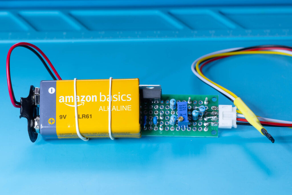
The original design of K&J Magnetics used a flying leads circuit to realize the magnetometer. For stability and usability reasons, I decided to realize it on a perfboard instead. The build of the circuit on the perfboard is straightforward. Only half the area (12×6 holes) of the perfboard is used for the actual circuit, the rest is reserved for the 9V battery (to make the magnetometer more compact). I leave the concrete placing of the parts on the perfboard and their wiring as homework 😉. Most, if not all of it can be easily derived from the following pictures:
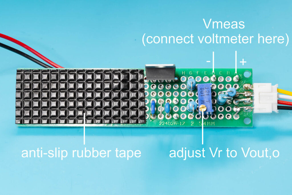
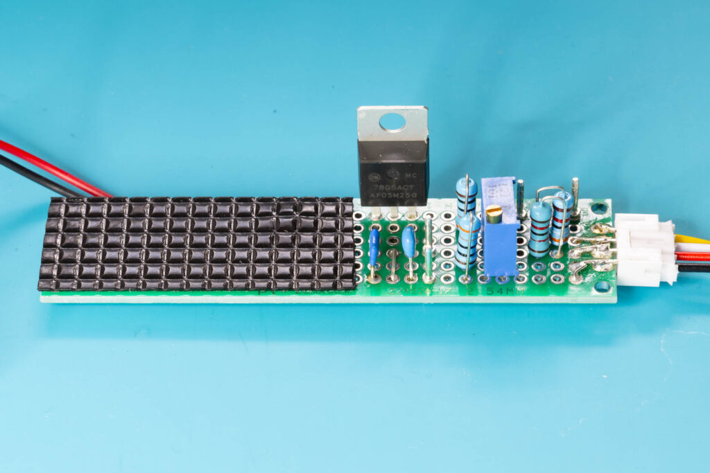
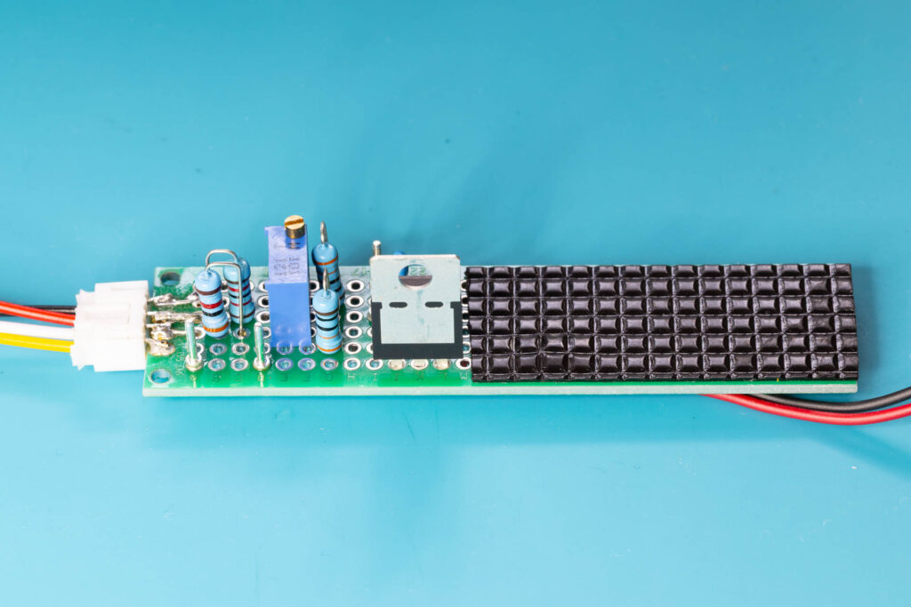
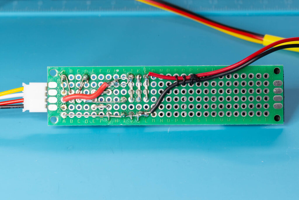
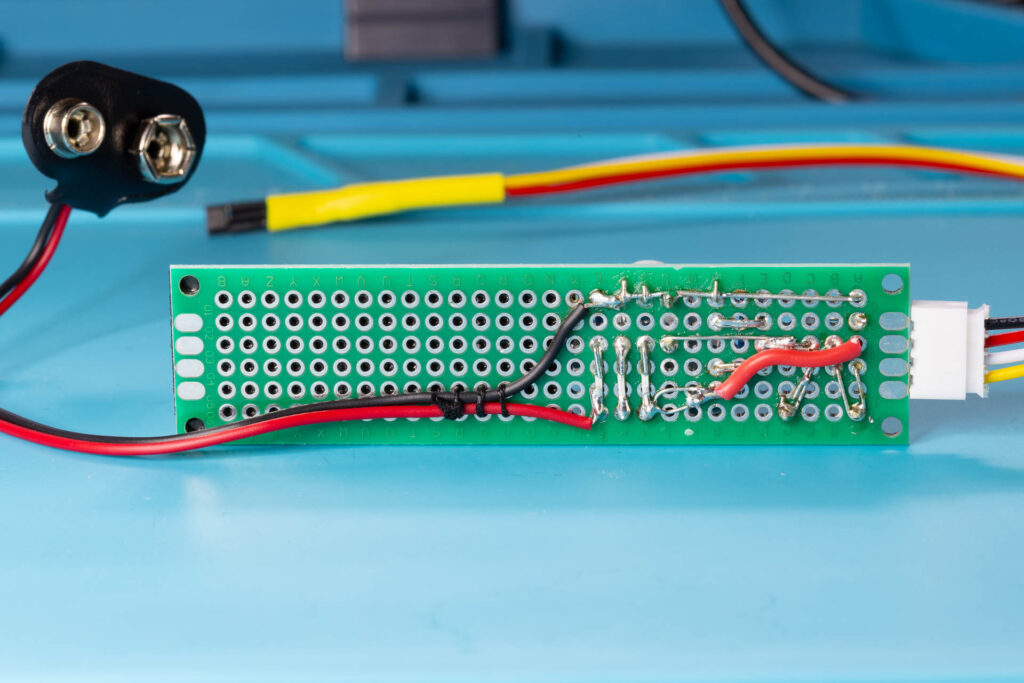
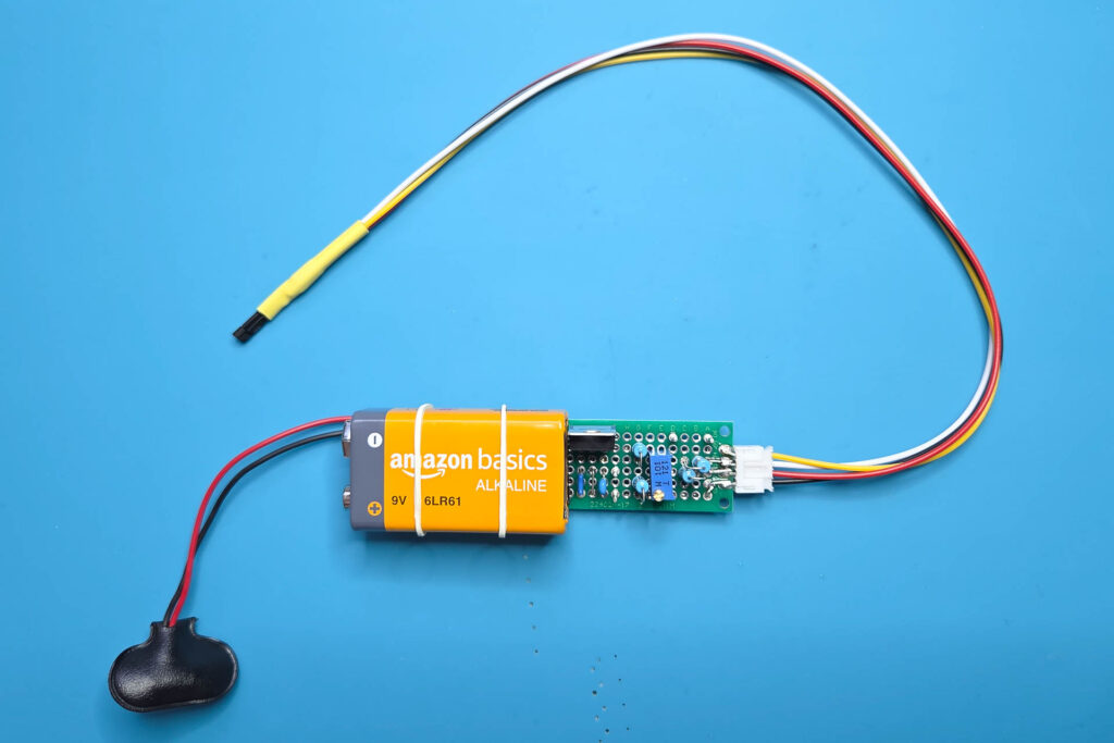
I decided to connect the Hall sensor to the circuit via a JST PH2.0 socket/plug combination and 30cm long, flexible wires. The idea behind this is that I can easily replace the Hall sensor if it breaks or I need a version with longer wires. Maybe even connecting a more modern Hall sensor like the A1308 instead (might require some changes of the circuit). For simplicity, you can also solder the wires directly to the perfboard. After soldering the wires to the Hall sensor I would suggest to reinforce the solder joints with heat-shrinking tubes. Like one tube per sensor terminal and then another, larger one across all three terminals. Otherwise, you could easily break one of the tiny terminals while handling the sensor.
How to Use the Magnetometer
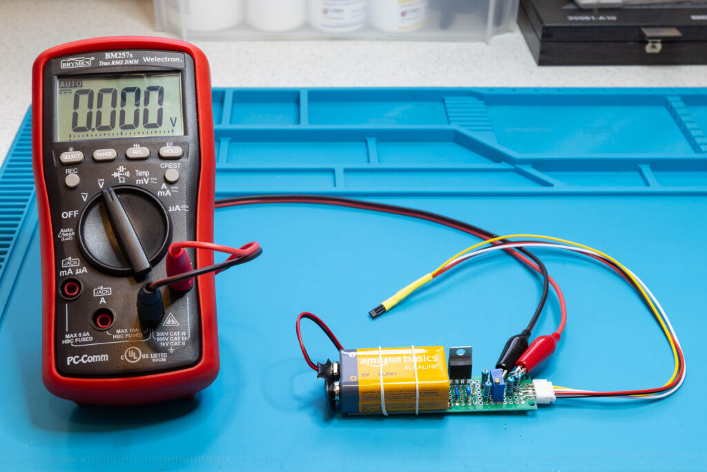
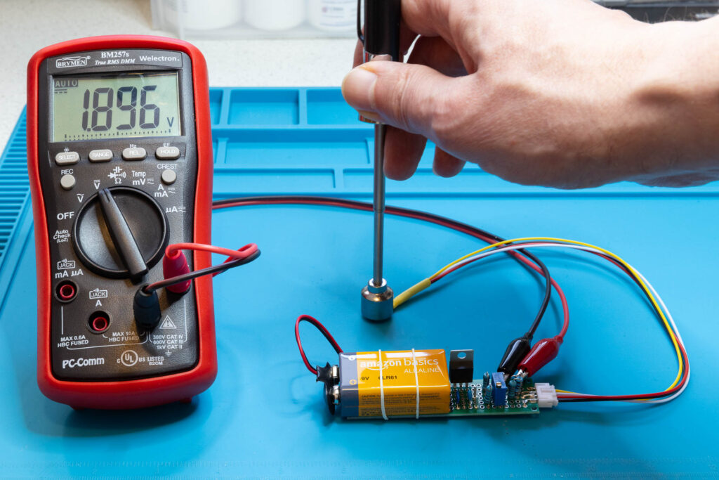
First, place the 9V battery on the perfboard and secure it with a couple of small rubber bands. Then, connect the battery to the circuit using the battery clip. Connect your voltmeter to the test points (solder terminals) of the perfboard. Pay attention to the correct polarity! Switch the voltmeter on and select a DC voltage range of at least 2V that has a 1mV resolution. Make sure that the Hall sensor is far away from any significant magnetic field (the Earth’s magnetic field is OK 😄). When you use the magnetometer for the first time or the last time was already long ago, the voltmeter may display a value other than 0.000V. If this is the case, use the precision trimmer on the perfboard to adjust the display to exactly 0.000V. Now, the magnetometer is ready for use. As already pointed out above, align the branded face of the Hall sensor towards the source of the magnetic field you want to measure.
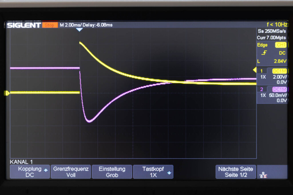
If you’re interested in the temporal evolution of the strength of a magnetic field, you can also connect the magnetometer to an oscilloscope. Although the A1302 isn’t particularly fast (output bandwidth of 20 kHz according to its data sheet), you should get about 10-20 samples per millisecond. In the picture shown below, the purple line represents the measured change of a magnetic field of a so-called “combination” magnet (electromagnet with permanent magnet as core) when a capacitor is discharged via its coil. In this example, the horizontal resolution is 2msec per division.
After you have finished the measurements, don’t forget to remove the battery clip from the 9V battery (due to space restrictions, there is no explicit ‘Power On/Off’ button). Mainly due to the voltage regulator and the voltage divider for the reference voltage, there is a constant current flow of about 17mA. This would drain the battery within a few days.
That’s all.