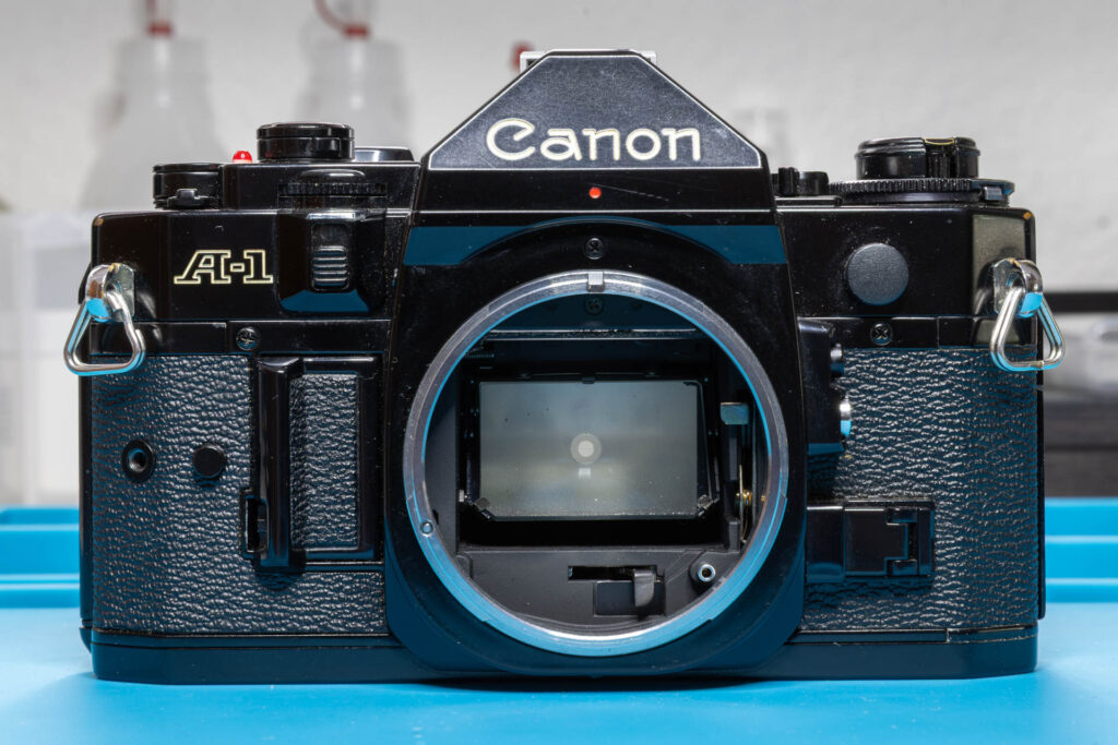
Disclaimer: The repair procedure I present in this post is inspired by the official service manual and renowned repair articles but mainly reflects my own experience. The description may be incomplete and might even contain errors. Consider that I am just a self-taught hobbyist, not a trained professional. Copy this procedure at your own risk! Also, consider that any attempt to disassemble and repair a camera carries a certain risk to worsen its condition or to even breaking it completely.
Especially, consider that this procedure contains a delicate soldering job, mainly in tight spaces. If necessary, practice your soldering skills beforehand. The repair of a Canon A-1 is not the right time to learn how to solder “on-the-job”.
When a Canon A-1 has to be repaired, the process often requires the removal of the mirror box (also called ‘mirror cage’ or ‘mirror assembly’). For example, when the shutter or auto diaphragm mechanism does not work. The mirror box is the assembly that contains the lens mount, the battery door, the prism, the mirror, and the mechanisms to operate the mirror and the lens diaphragm. In this post, I present the removal steps that are necessary in the order that works best for me.
Model variations: The Canon A-1 was produced from 1978 to 1985. In this post, I use a copy from 1981 (serial number 166xxxx) for illustration. During its production, the camera underwent some minor technical changes, mainly in the early years 1978-79. If the changes are known to me and they are relevant for the topic of this post, I will mention them.
Preparation
First, follow the procedure described in this blog post to remove the top cover of the Canon A-1.
If not done yet, also remove the action grip.
Tools
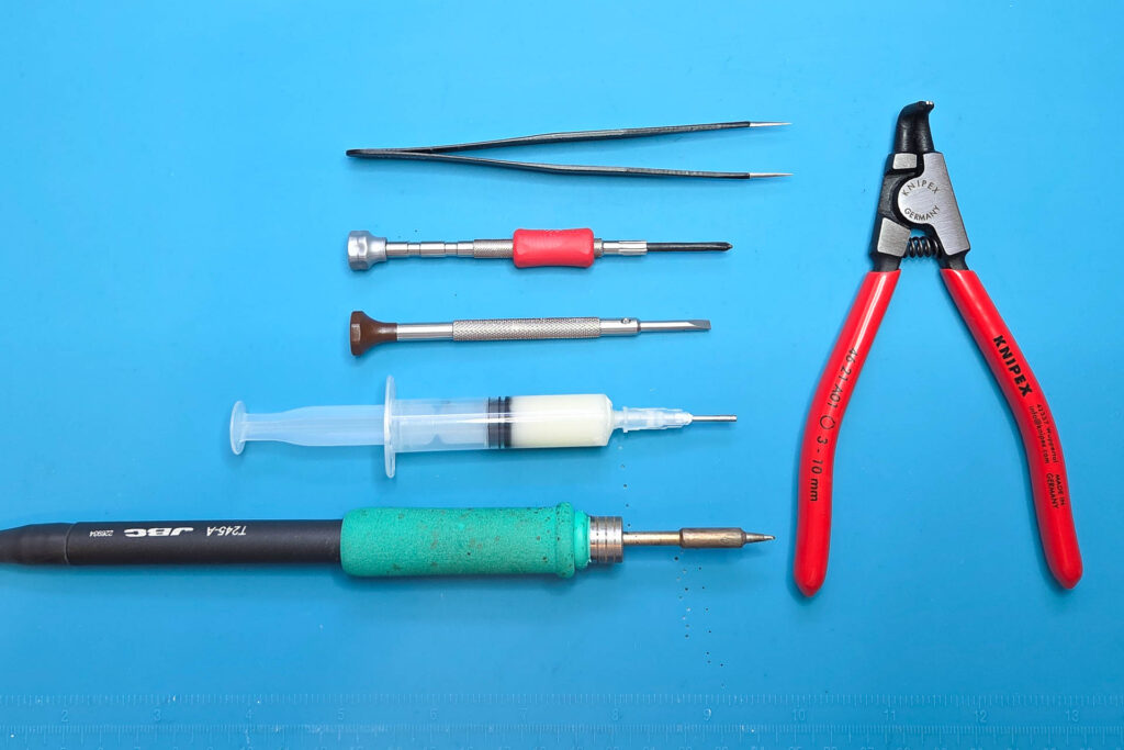
To remove the mirror box of a Canon A-1, you need a certain set of tools. These are my recommendations:
- JST screwdriver #00
(A Phillips screwdriver PH00 or PH0 might work “somehow” but be aware that it might damage the screw head.) - flat-head screwdriver ≥ 3mm (blade thickness ≤ 0.5mm!)
- tweezers with sharp points
- circlip / snap ring pliers for small rings, like a Knipex 46-21-A01
- adjustable soldering iron with small tip
(I use a JBC BT-2BWA soldering station with a C245-906 cartridge with small tip [chisel 1.2×0.7mm]. For leaded solder, I operate it at 300 °C.) - [optional] acid-free soldering flux (might reduce the desoldering time)
- [optional, not on picture] adjustable heat gun
Step 1: Desolder the Wires
Consider that during its production run from 1978 to 1985, some of the wiring of the Canon A-1 seems to have been changed. Therefore, always double-check if you desolder the correct wire. Do not just rely on the colors of the wires. They may have changed as well, both in the factory and during later repairs. It is highly recommended to take detailed, sharp photos of all the relevant wires before desoldering them.
Desolder Four Wires from SV Circuit Board
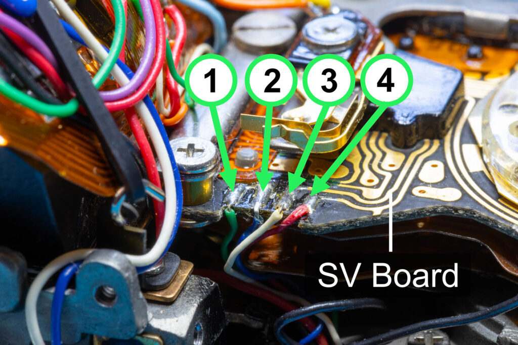
Desolder the four wires marked in the picture above from the SV ([Film] Speed Value) circuit board. The wires serve the following purposes:
- Wire 1 (green) and wire 3 (white) connect to the ‘A/M Change’ switch (also called A-MSW or SW11). The switch is OFF if you set the aperture of the lens to ‘A’ (= automatic mode) and ON if you set the lens to any specific aperture (= manual mode). The switch is activated by the ‘Auto’ pin of the lens.
- Wire 2 (blue) and wire 4 (red) connect to the ‘Stop-down’ switch (also called SPDW). The switch is ON when you pushed the stop-down lever.
Desolder Four Wires from Main Flexible Board
Before you continue desoldering, you should remove the black rubber band that holds the main flexible board down. Otherwise, you might burn it.
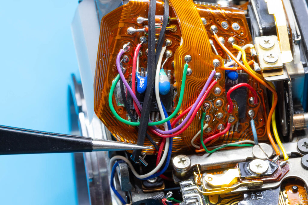
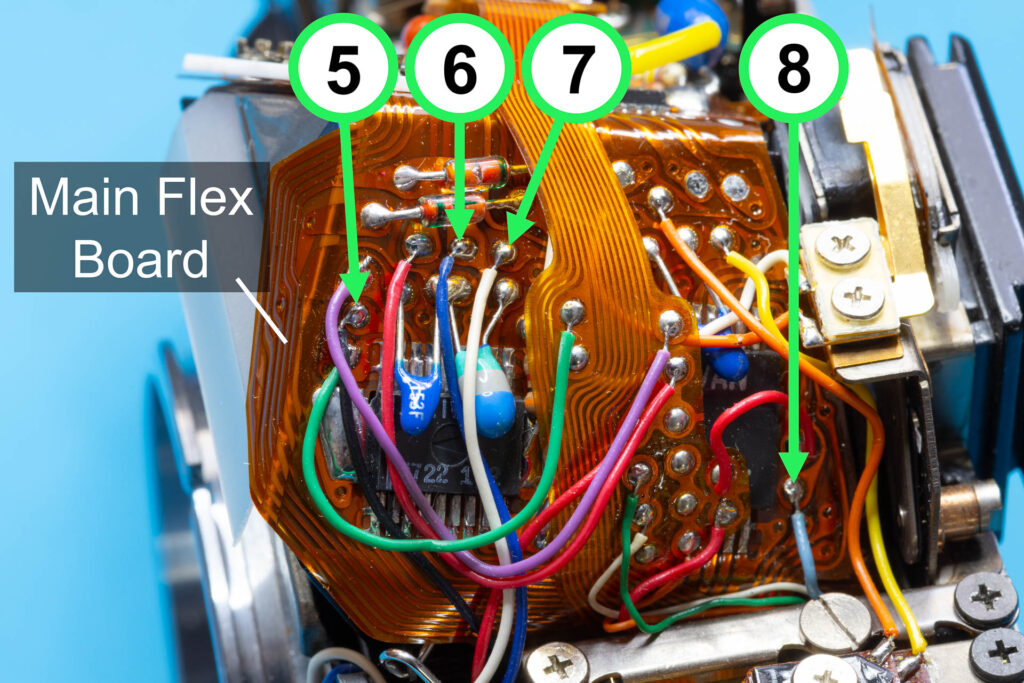
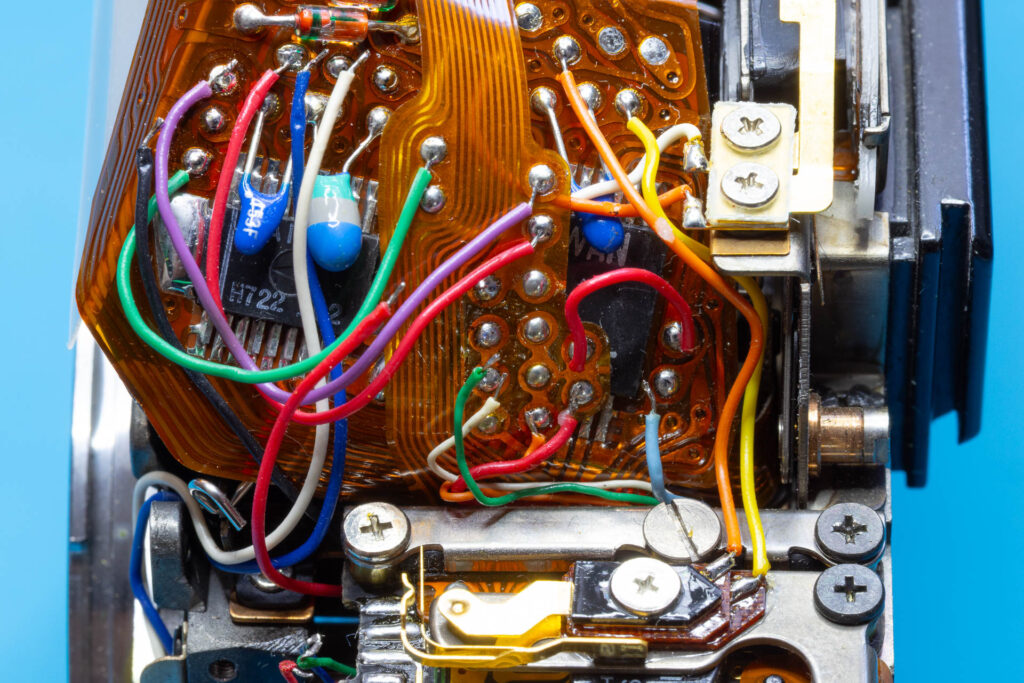
Desolder the four wires marked in the picture above from the main flexible board. The wires serve the following purposes:
- Wire 5 (black or yellow) connects to the aperture control magnet (also called MG1).
- Wire 6 (blue) connects to the ‘Exposure Memory’ switch (also called ‘AE Lock’ switch or SW6). When pressed, the switch locks the exposure value (EV) currently measured until the switch is released (alternative method of exposure compensation).
- Wire 7 (white) connects to the ‘Exposure Preview’ switch (also called LM SW). When pressed, the LED display in the viewfinder displays the shutter speed set and the aperture the camera would choose in the current lighting situation.
- Wire 8 (light-blue) connects to the ‘Segmented Aperture Value Electrode’ (SAVE) plate. This plate is used to detect the current aperture of the lens. The wire transmits the AECG signal from the plate.
Desolder Five Wires from AT Flexible Board
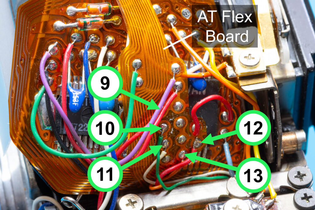
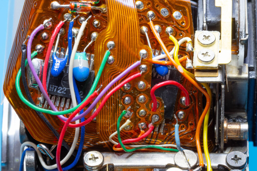
Desolder the five wires marked in the picture above from the AT (Aperture/Time) flexible board (ribbon board above the main flexible board). The wires serve the following purposes:
- Wire 9 (red) connects to the aperture control magnet (also called MG1).
(Consider that there are other versions of the Canon A-1 where this wire is not soldered to the AT flexible board but to the main flexible board, near the solder joint of wire 5.) - Wire 12 (red) connects to the ‘Segmented Aperture Value Electrode’ (SAVE) plate. It transmits the SAVE signal, a series of low-active pulses that the CPU uses to determine the current aperture of the lens.
- Wire 10 (green), wire 11 (white), and wire 13 (orange) also connect to the ‘Segmented Aperture Value Electrode’ (SAVE) plate. They are called ‘SAVE adjust’ wires since they allow to correct small deviations in the aperture closing mechanism.
Attention: The SAVE adjust wires 10, 11, and 13 may be connected to different soldering points of the AT flexible board in different copies of the camera. Always take a photo before desoldering the wires to make sure that you solder them back to the correct soldering points when you install the mirror box. Don’t just rely on the picture above, it only shows one of several possible versions. For more details, see this blog post.
Step 2: Open the Flexible Board Connectors
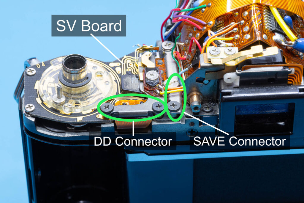
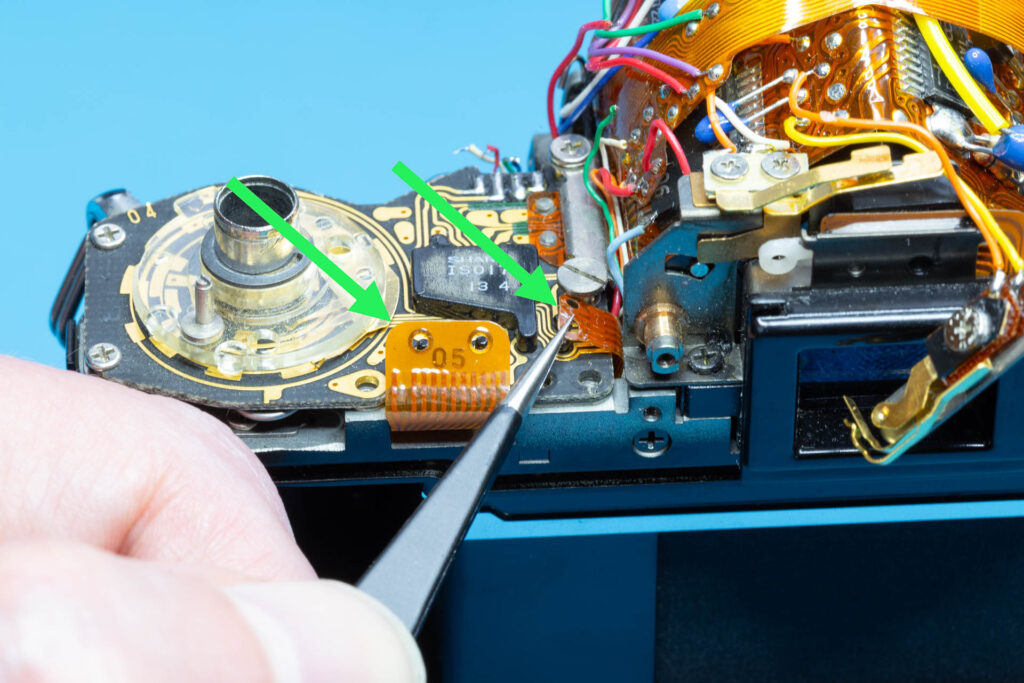
Two flexible boards leading to the mirror box are connected to the SV circuit board via mini connectors. You have to open these connectors by unscrewing their connector plates to disconnect the flexible boards.
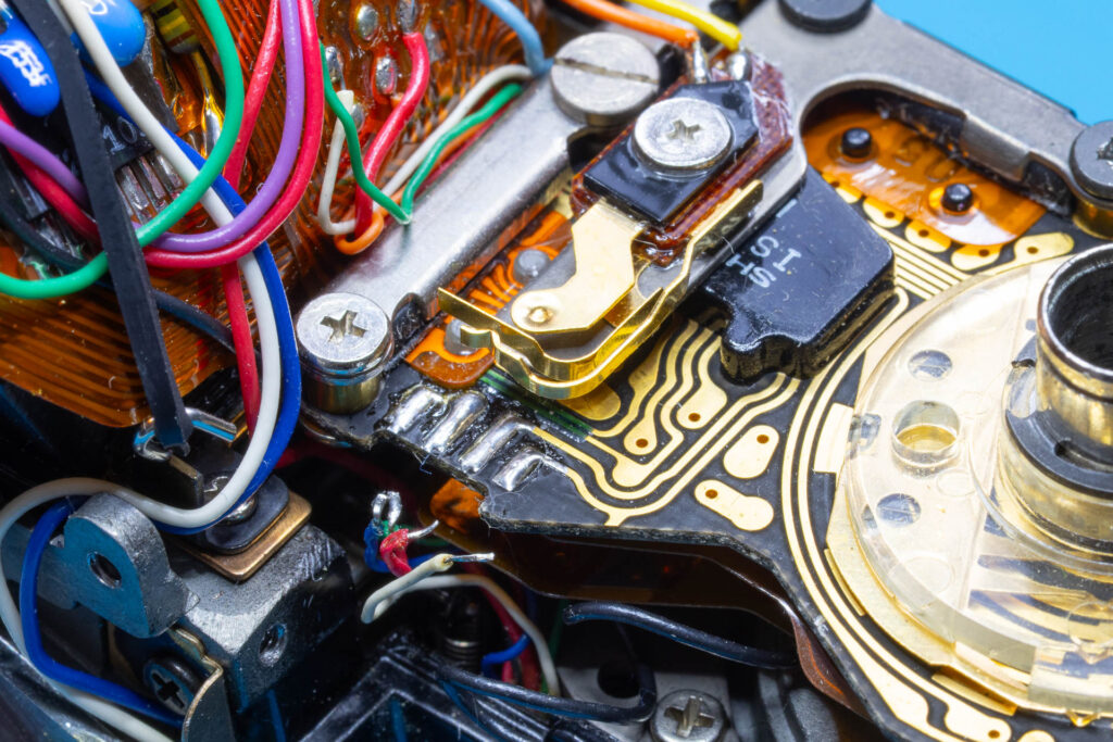
First, loosen the slotted screw of the SAVE (‘Segmented Aperture Value Electrode’) connector. Don’t unscrew it, just loosen it by about one turn in counter-clockwise direction. If you would remove this screw, some parts would fall off from under the SV circuit board. Then, remove the cross-head screw of the connector and lift off the SAVE connector plate. Afterwards, remove the two screws of the DD (‘Decoder Driver’) connector, lift off the connector plate and put it to the right. Finally, use tweezers to lift off the flexible boards from the connectors. Be careful to not kink or tear the flexible boards.
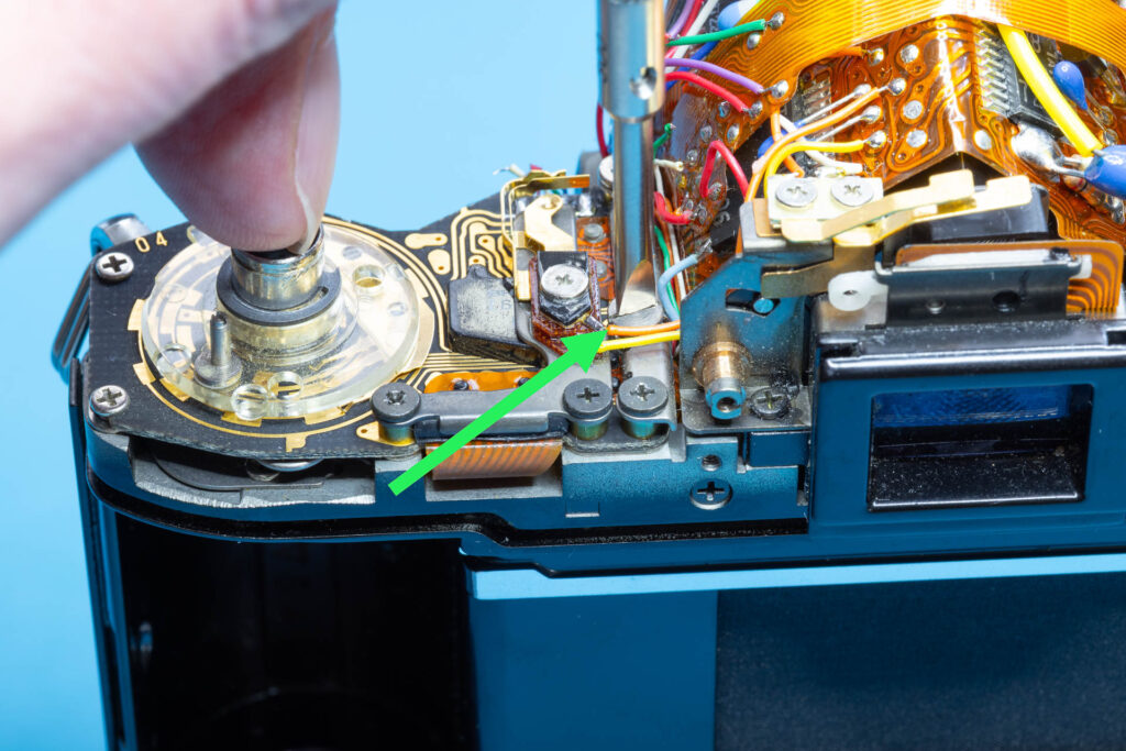
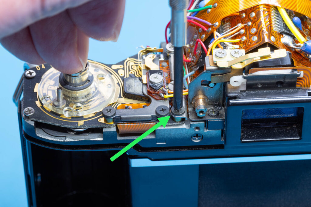
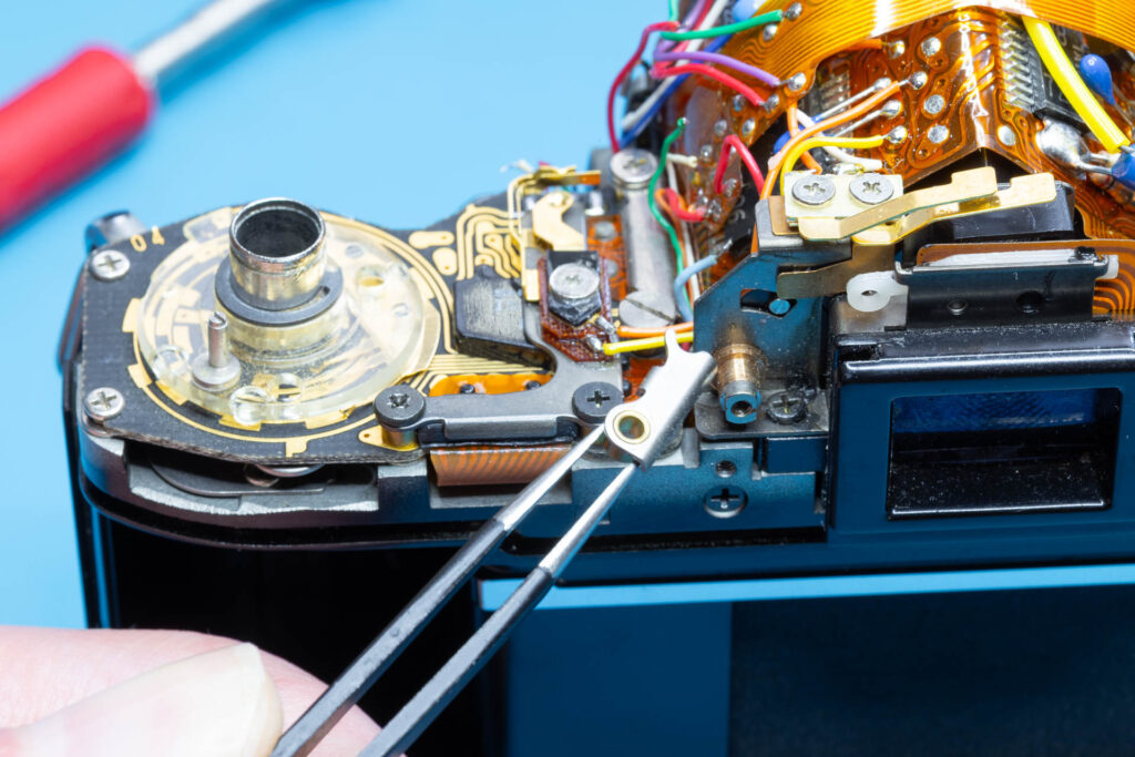
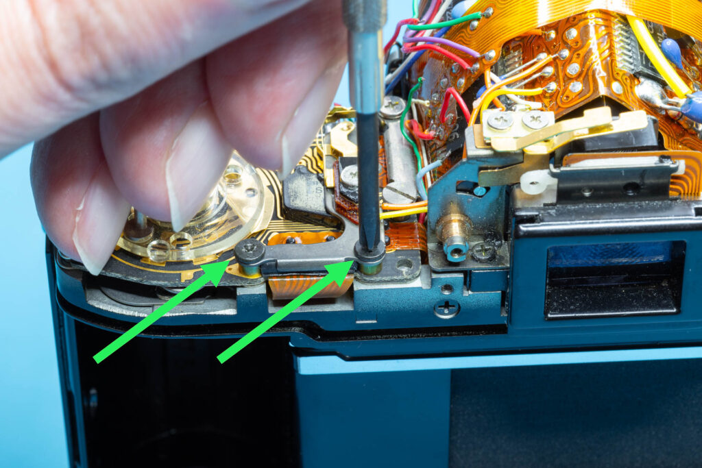
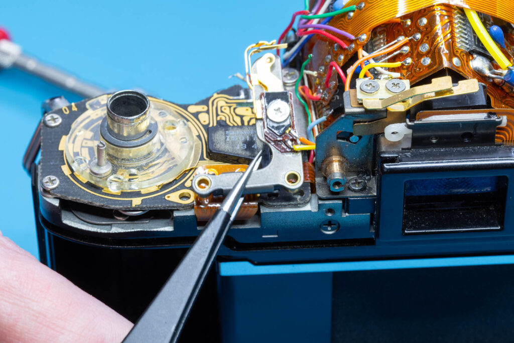
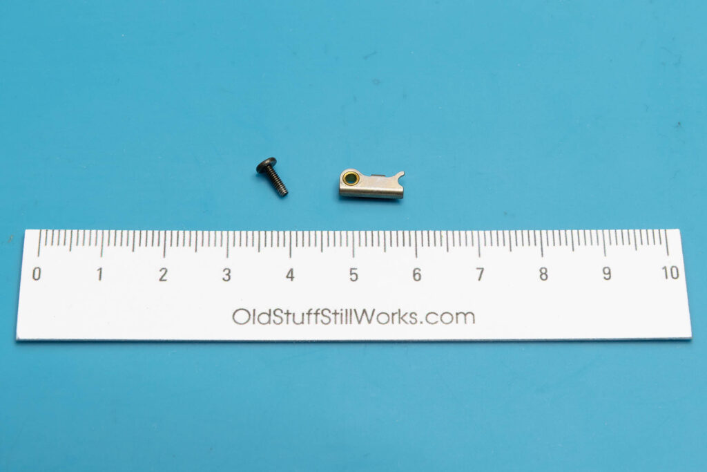
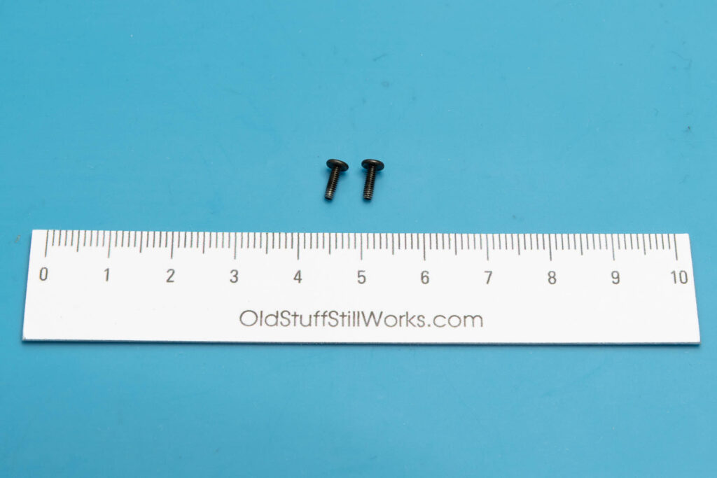
After this step, the following parts are removed (in removal order from left to right): one screw (1.65×5.3mm), SAVE connector plate, two screws (1.65×5.5mm), The DD connector plate is still attached to the main flexible board via two wires.
Step 3: Remove the ASA Brush Plate
On the Canon A-1, the user sets the current ASA film speed using a rotary switch. From top to bottom, this switch consists of the following components:
- a rotary dial that can lock into several positions, one per supported ASA value
(Already removed during removal of the top cover of the camera.) - a transparent brush plate with tiny contact wipers that rotates with the dial
- a fixed code plate with contacts (part of the SV circuit board)
Depending on the ASA setting (= position of the dial), the contact wipers connect certain contacts of the code plate and translate the ASA setting into the corresponding binary value.
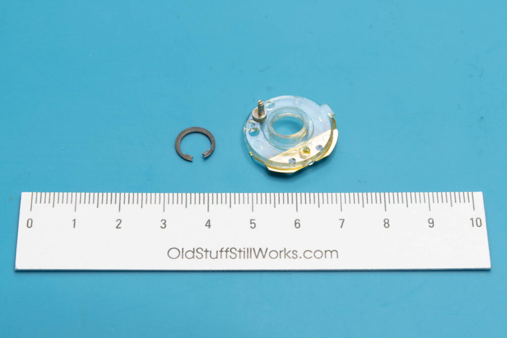
First, remove the snap ring securing the ASA brush plate. For this, the best tool is a circlip / snap ring pliers for small rings, like a Knipex 46-21-A01. Then, lift off the brush plate. Be careful to not bend or break any of its tiny contact wipers.
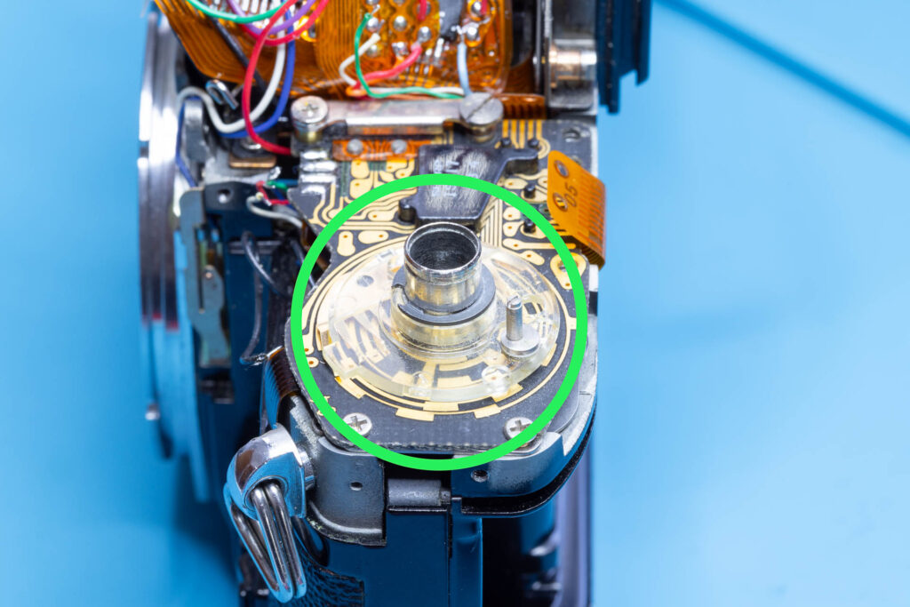
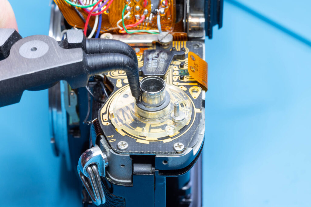
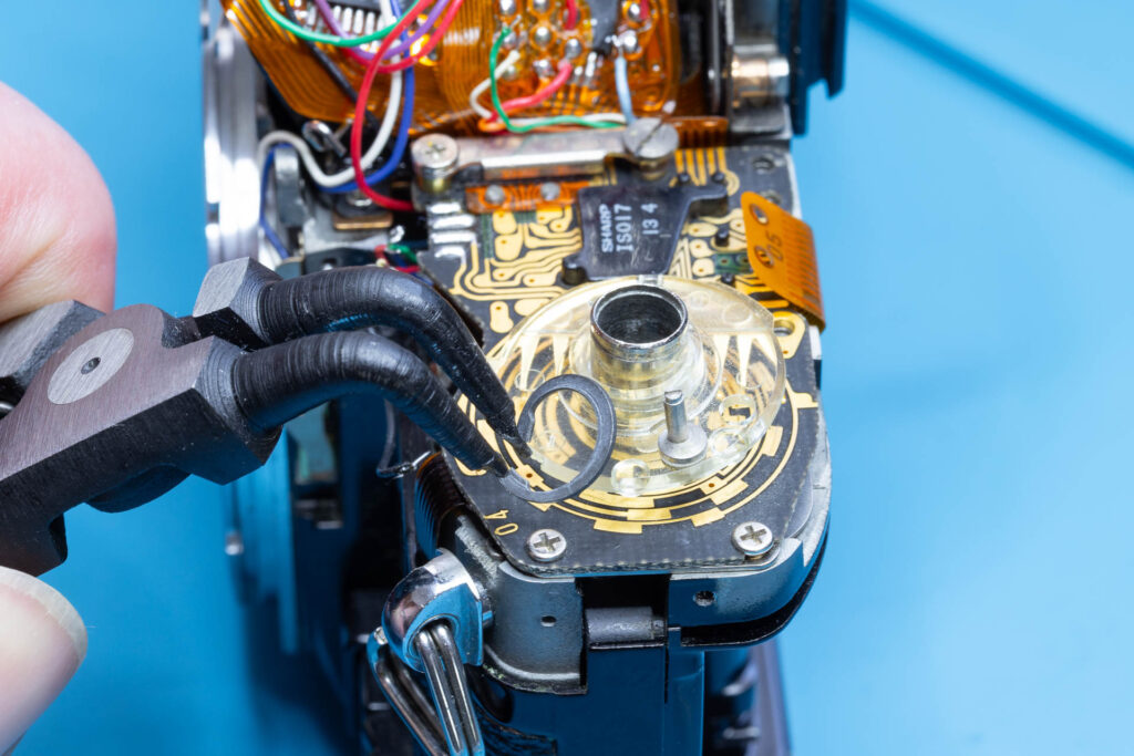
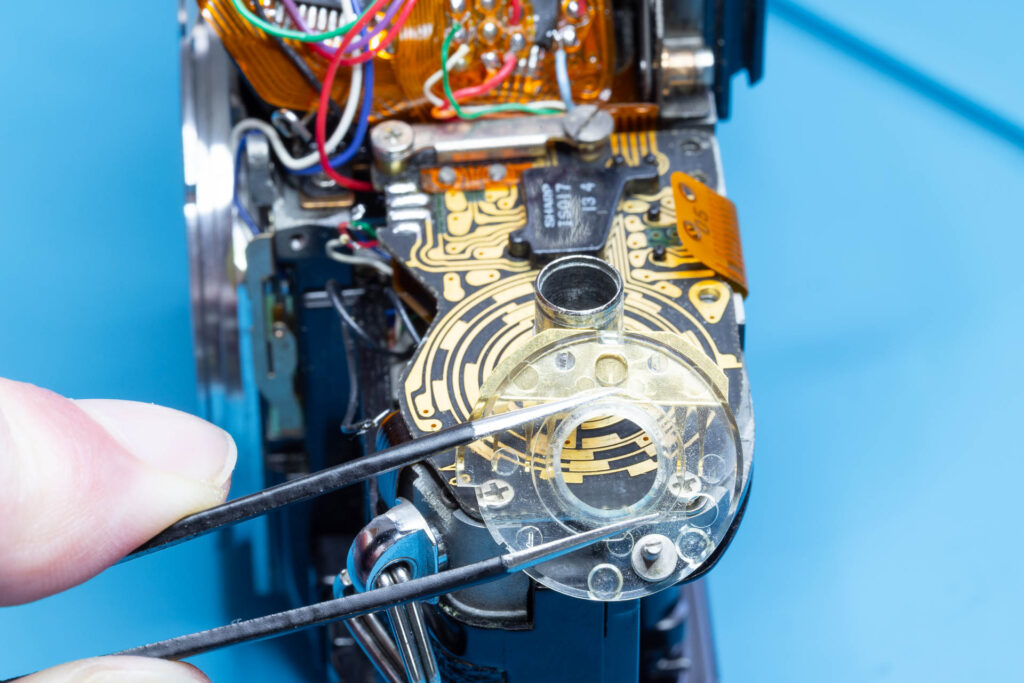
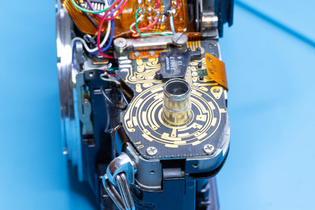
After this step, the following parts are removed (in removal order from left to right): snap ring, ASA brush plate.
Step 4: Lift the SV Circuit Board
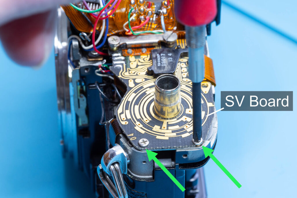
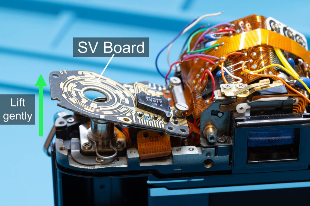
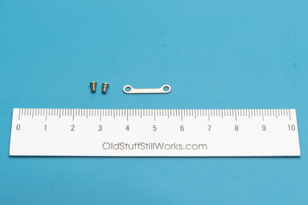
The flexible boards attached to the mirror box have to be pulled out from under the SV circuit board when the mirror box is removed. To decrease the risk of damaging or tearing these flexible boards, the SV board should be lifted beforehand. First, remove the two screws holding the SV board. Then, pull out the small metal bar that is placed under the edge of the SV board. Finally, lift the unscrewed side of the SV board gently by about 2cm. The other side of the SV board is still connected to the AT flexible board. This connection should not be put under too much stress. When you lift the SV board make sure that the curved ends of the SAVE and DD flexible boards slip under the SV board.
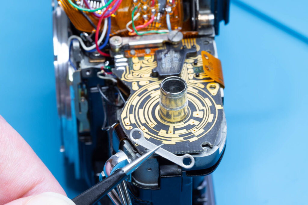
After this step, the following parts are removed (in removal order from left to right): two screws (1.95×2.9mm), metal bar of SV board.
Step 5: Remove the Eyepiece Screws
Left and right of the eyepiece there are two screws that connect the mirror box to the camera chassis. Remove these screws.
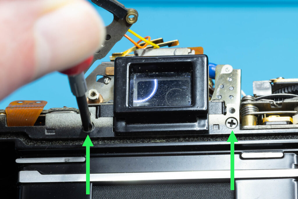
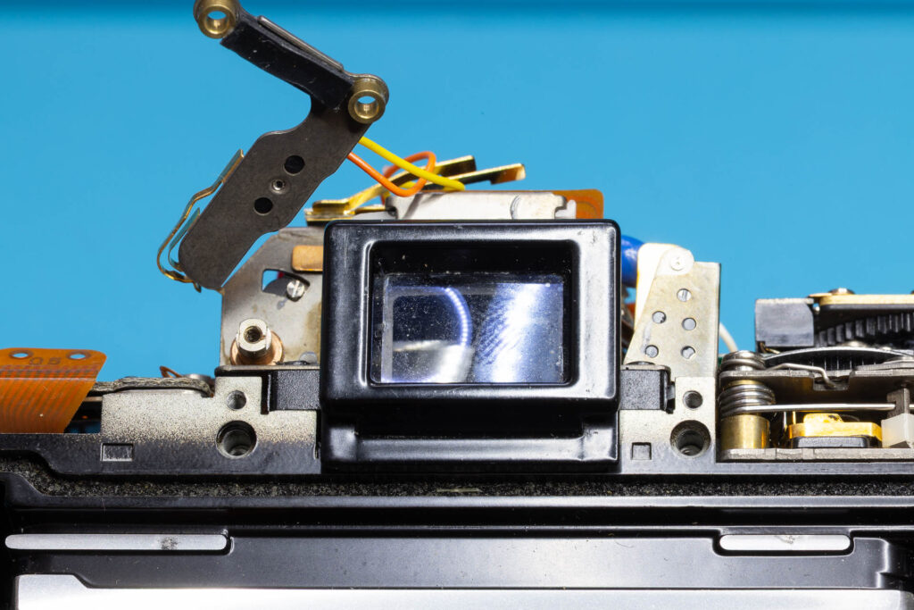
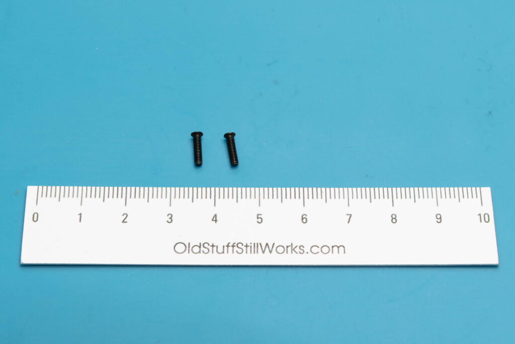
After this step, the following parts are removed: two screws (1.90×7.3mm).
Step 6: Remove the Front-Facing Leatherette
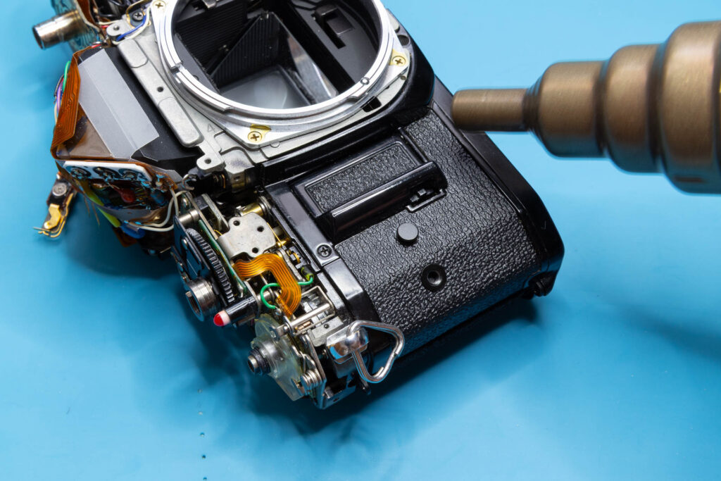
Four of the five remaining screws connecting the mirror box to the camera chassis are hidden under the leatherette on the front of the camera. Therefore, the leatherette (faux leather) has to be removed. There are different methods to do this, depending on how well the glue holds and also on personal preferences. You can try to peel off the leatherette without any preparatory steps, you can warm up the leatherette or soak it in alcohol beforehand. In any case, be careful to not tear the leatherette. You should try out for yourself which method works best for you. I prefer the “warm up” method using a heat gun or hair dryer. However, you have to ensure that the air blown onto the leatherette is not warmer than 50-60 °C.
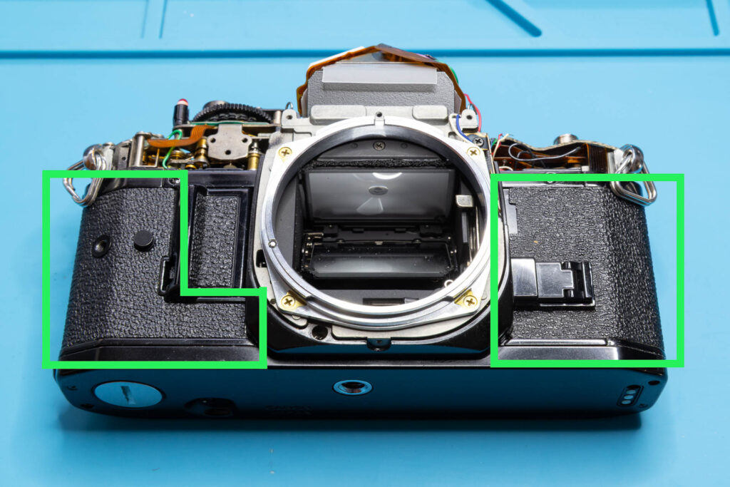
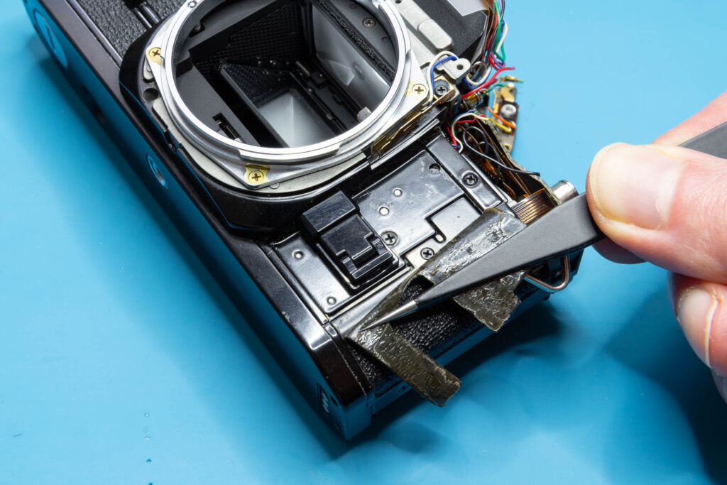
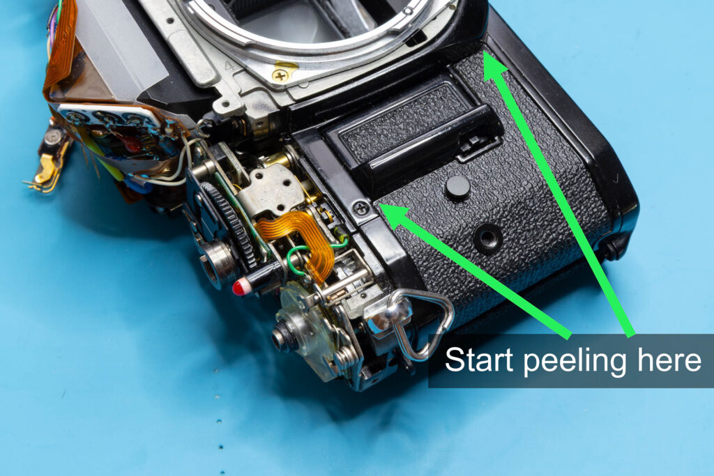
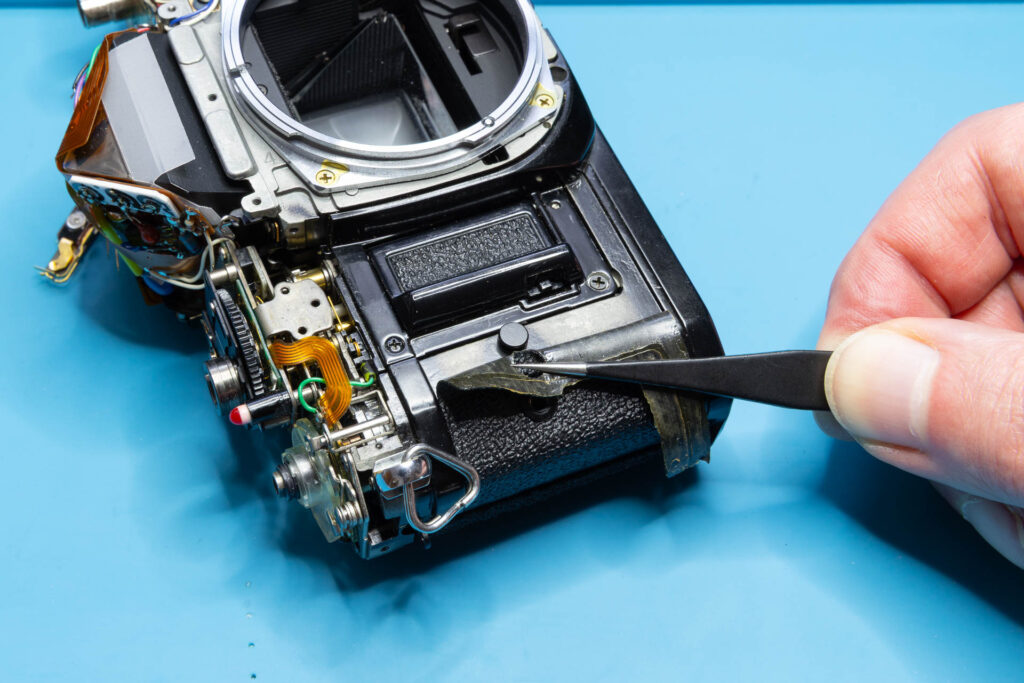
First, peel off the right-side leatherette (where the stop-down lever sits). Use tweezers with sharp points to get under the leatherette at the places shown on the picture below. Gently peel off the leatherette to the right side. After you have peeled off about 1cm of the edges of the leatherette you can grab it with your fingers and continue pulling. You can remove the leatherette completely or you can leave its rightmost 15-20mm glued on. I prefer the latter since it makes re-glueing the leatherette much easier.
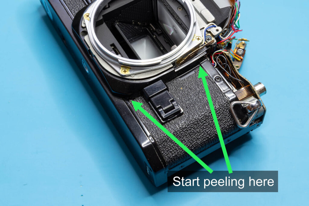
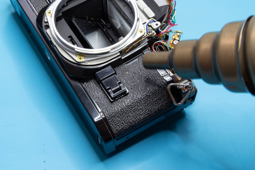
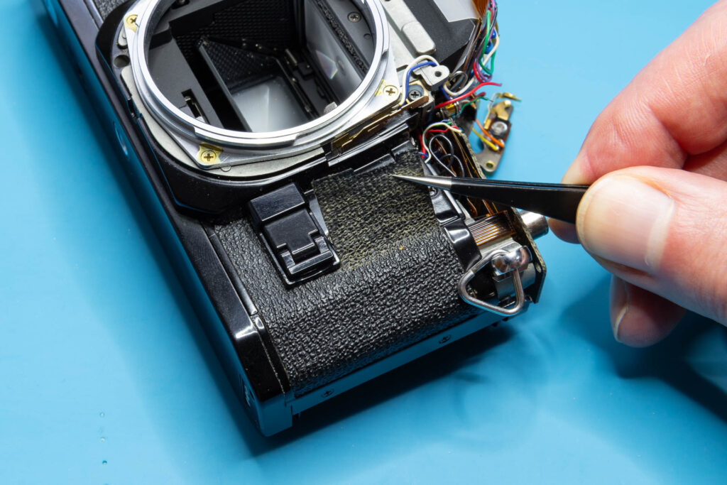
Then, peel off the left-side leatherette (where the battery door sits). Use tweezers with sharp points to get under the leatherette at the places shown on the picture below. Continue like described for the right-side leatherette.
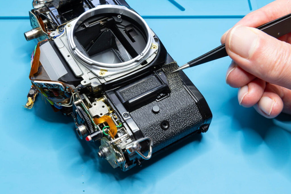
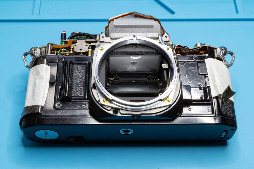
As said, I prefer to not remove the leatherette completely. I use some masking tape to get the loose ends of the leatherette out of the way.
Step 7: Unscrew the Mirror Box
The mirror box is connected to the camera chassis by five remaining screws (see positions in the picture below). Remove these five screws.
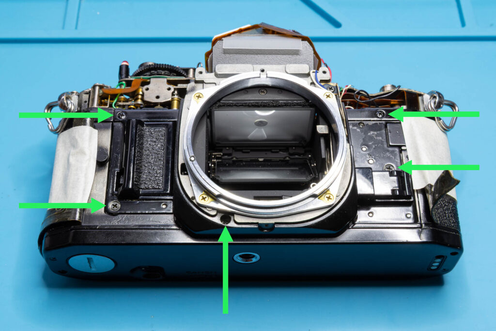
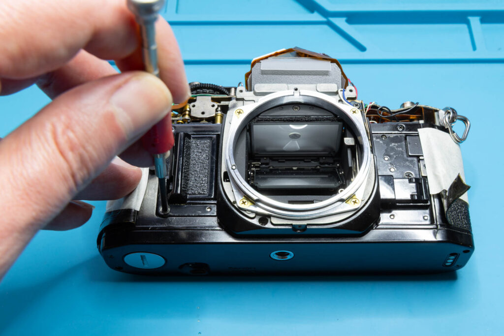
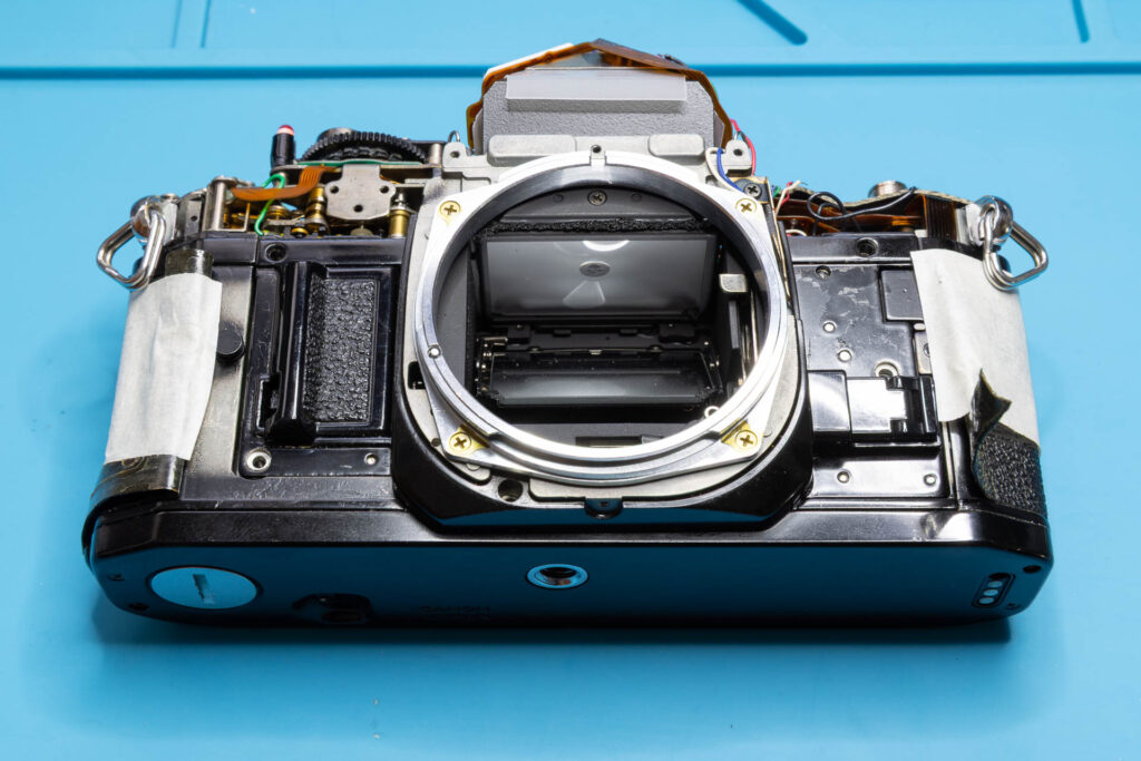
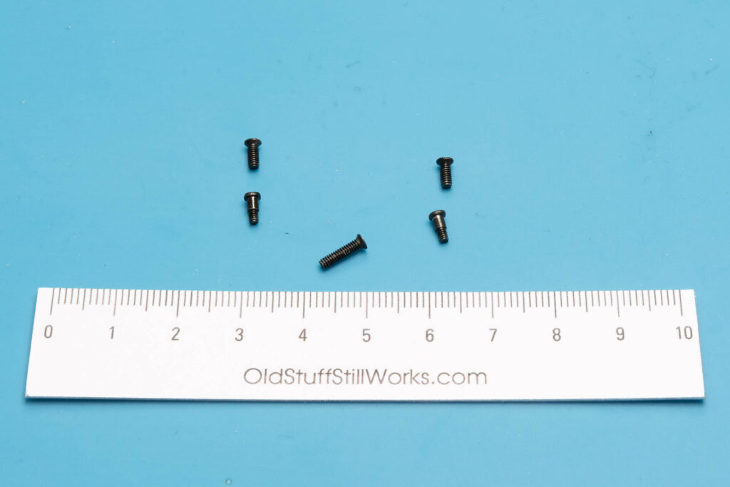
After this step, the following parts are removed (according to their position on the camera, from top to bottom): two screws (1.95×4.3mm), two partially threaded screws (1.65×4.4mm), screw (1.95×7.2mm). Don’t mix up these screws during reassembly!
Step 8: At Last, Remove the Mirror Box
After Steps 1 to 7, the mirror box is no longer mechanically connected to the camera chassis. You can grab the mirror box and pull it out carefully. Make sure that all its wires and the two flexible boards can slip underneath the SV circuit board without them getting stuck. It might help to wiggle the mirror box a bit left-right and up-down to free it from the camera chassis. Also, it might help to open the battery door and put a finger into the battery chamber for extra grip.
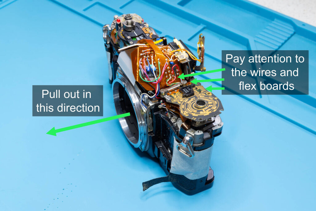
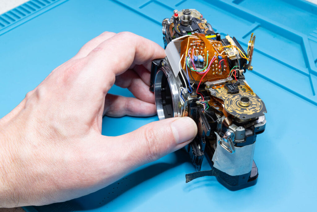
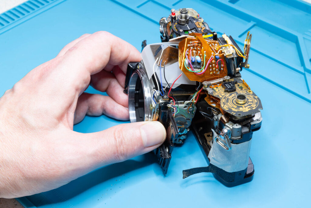
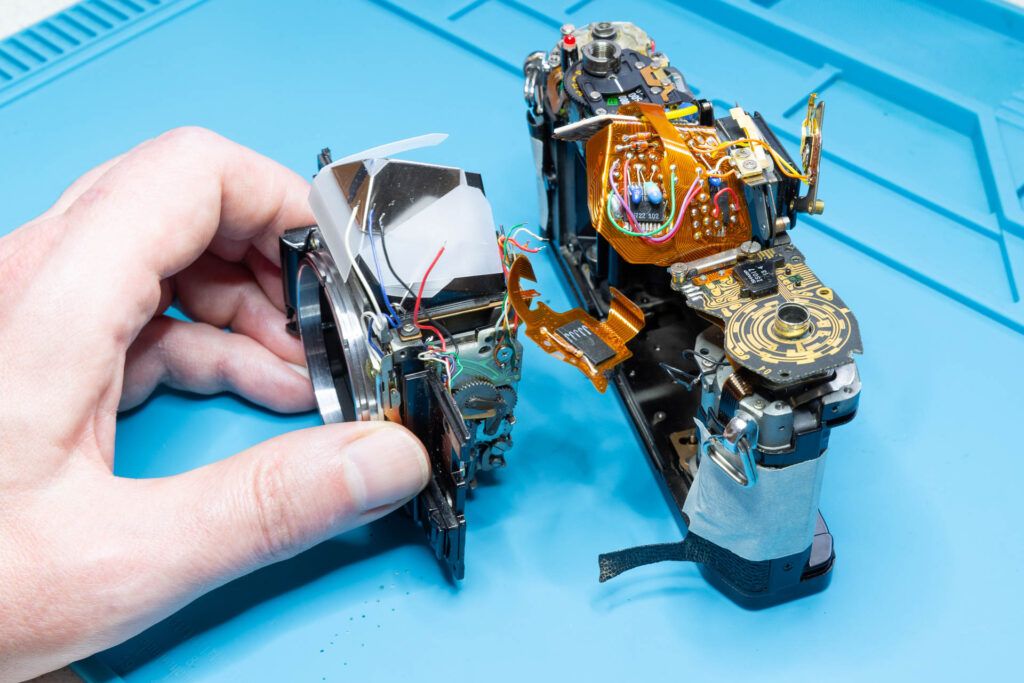
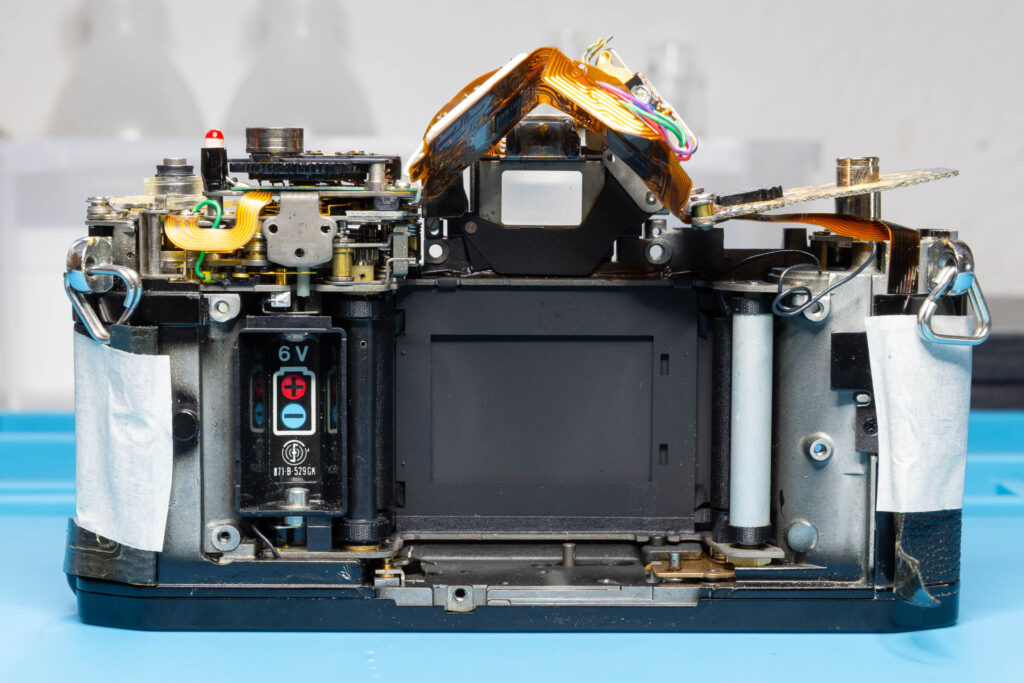
After this step, you have the mirror box and the camera chassis separated:
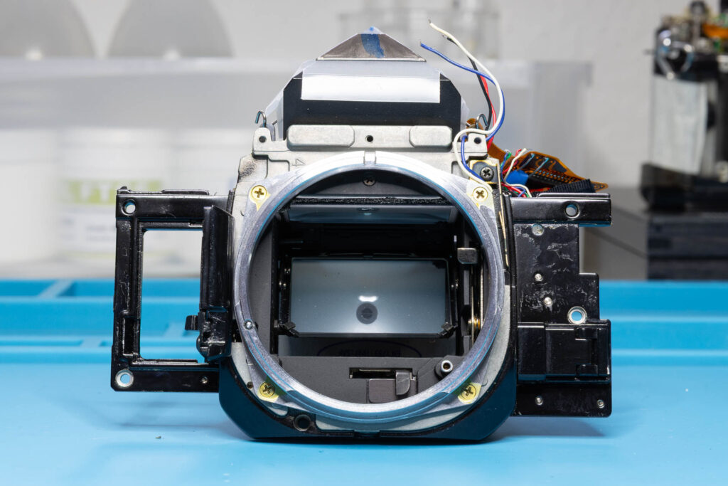
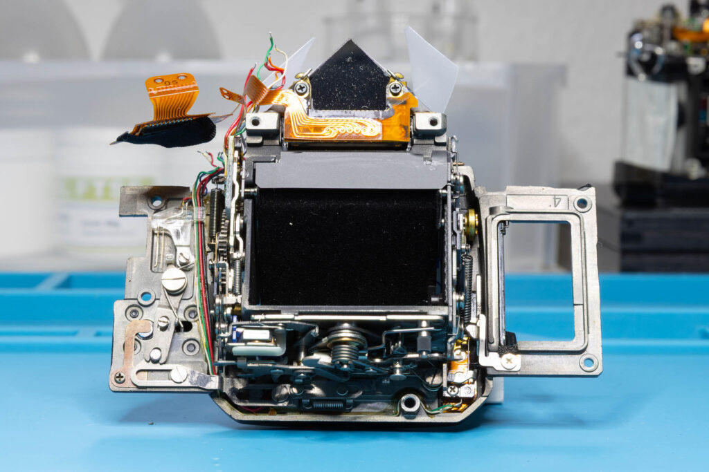
That’s all.