Disclaimer: The repair procedure I present in this post is inspired by the official service manual and renowned repair articles but mainly reflects my own experience. The description may be incomplete and might even contain errors. Consider that I am just a self-taught hobbyist, not a trained professional. Copy this procedure at your own risk! Also, consider that any attempt to disassemble and repair a camera carries a certain risk to worsen its condition or to even breaking it completely.
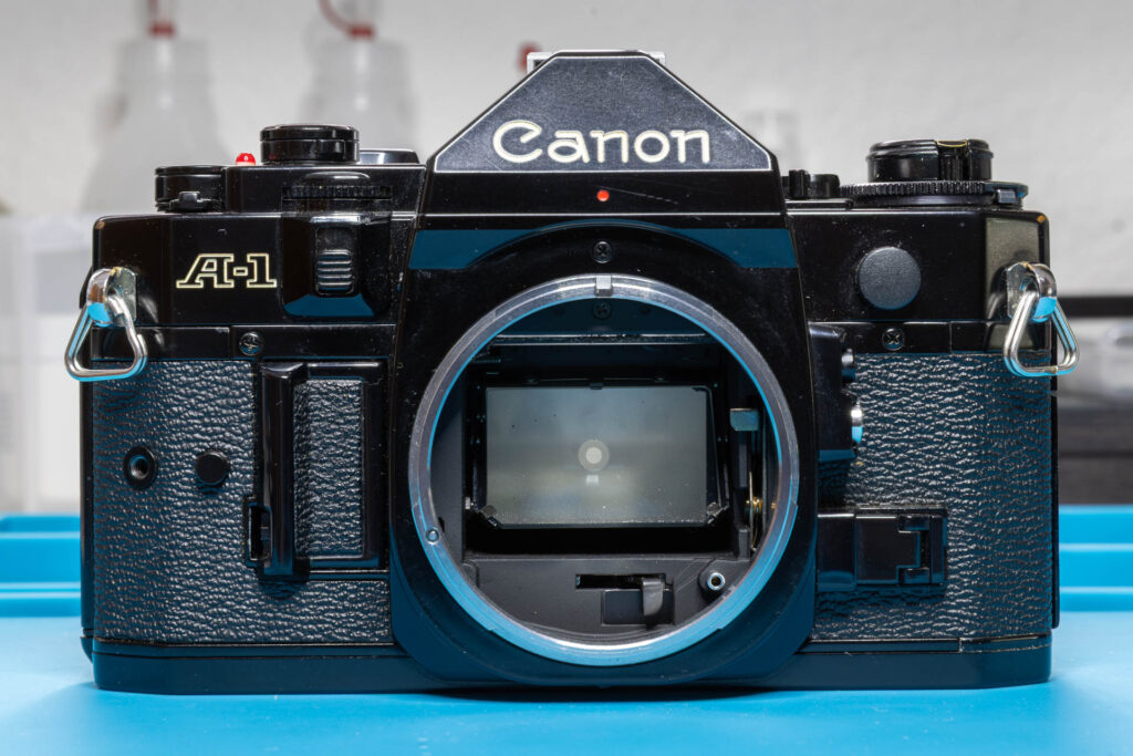
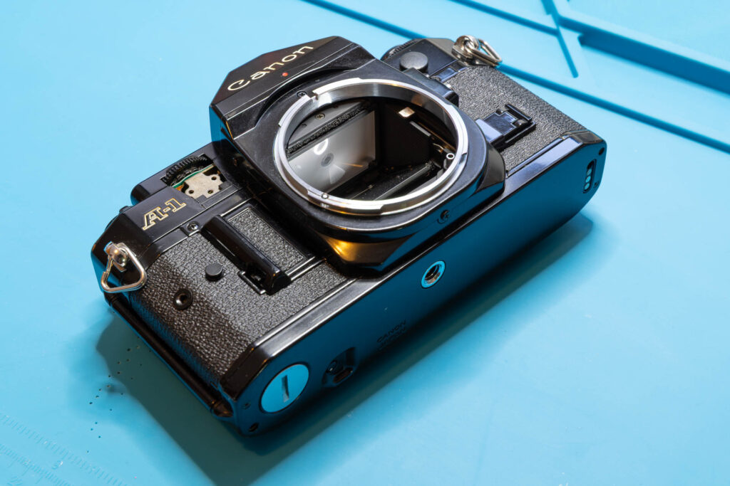
When a Canon A-1 has to be disassembled for CLA (Clean – Lubricate – Adjust) or repair, this process often starts with removal of its top cover. In this post, I present the removal steps that are necessary in the order that works best for me.
Preparation
In contrast to some other camera models, there are no mandatory settings that have to be made on the camera before disassembly. However, I have made a habit of making the following settings:
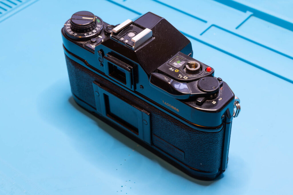
- I set the viewfinder display lever to ‘On’ (lever to the right, white dot visible).
(This is not important for disassembly but very important for reassembly. If the lever is in the ‘Off’ position then, you might damage the switch underneath when putting the top cover on.)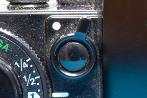
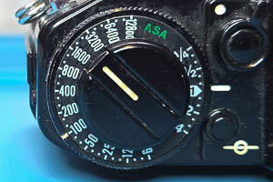
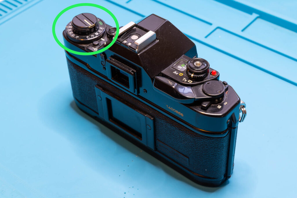
- I set the ASA film speed dial to ‘100’ and the exposure compensation dial to ‘1’ (= no compensation).
- I set the eyepiece shutter lever to ‘Open’ (lever in upright position). If the rubber eyecup is still on, I remove it.
(This will help if you want to clean the inside of the eyepiece or the prism.)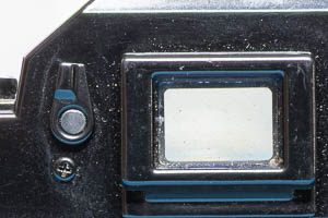
- I set the main switch to ‘A’ (= On, lever in upright position) and the multiple exposure lever to ‘Off’ (lever in downward position, red dot not visible).
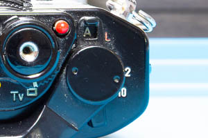
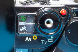
- I set the AE mode selector to ‘Tv’ (= time value = shutter priority) and the shutter speed to 1/1000sec.
It is also a good idea to remove the battery from the camera so that short-circuiting any wires or contacts accidentally during repair does to damage the camera.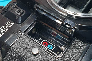
Finally, check whether there is still a film in the camera (happens occasionally when buying used cameras). You can do this by folding out the rewind crank and trying to turn it gently in clockwise direction. If you feel any resistance, there is still a film in the camera. If the rewind knob spins freely no film is loaded.
Tools
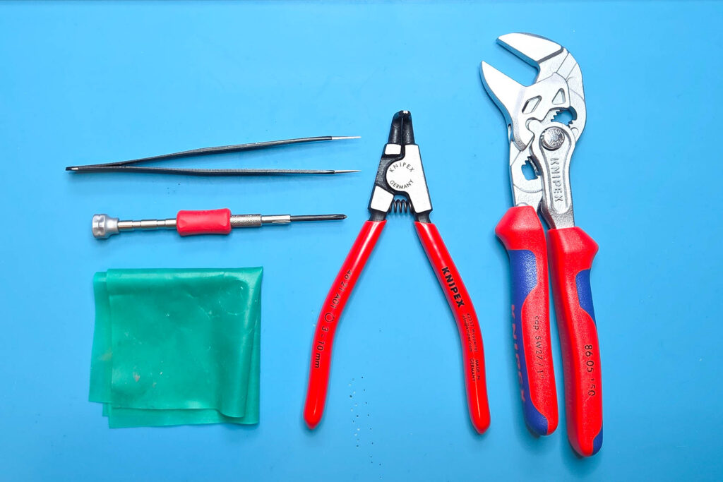
For removing the top cover of a Canon A-1, you only need a small set of tools. These are my recommendations:
- JST screwdriver #00
(A Phillips screwdriver PH00 or PH0 might work “somehow” but be aware that it might damage the screw head.) - tweezers with sharp points
- circlip / snap ring pliers for small rings, like a Knipex 46-21-A01
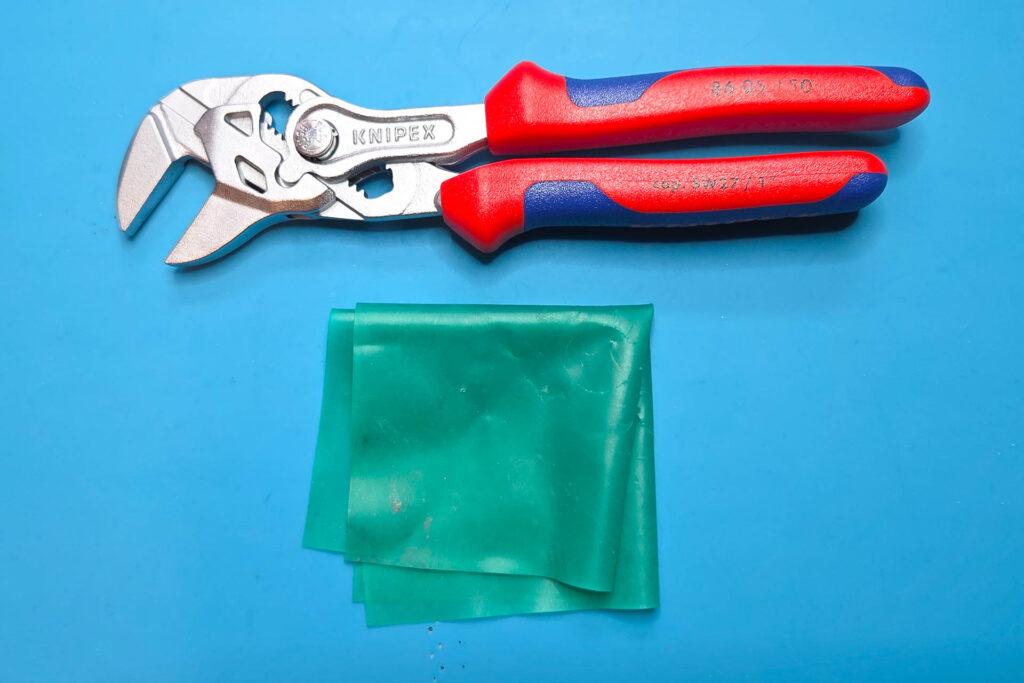
- pliers with smooth, parallel-set jaws, like a Knipex 86-05-150
- rubber cloth
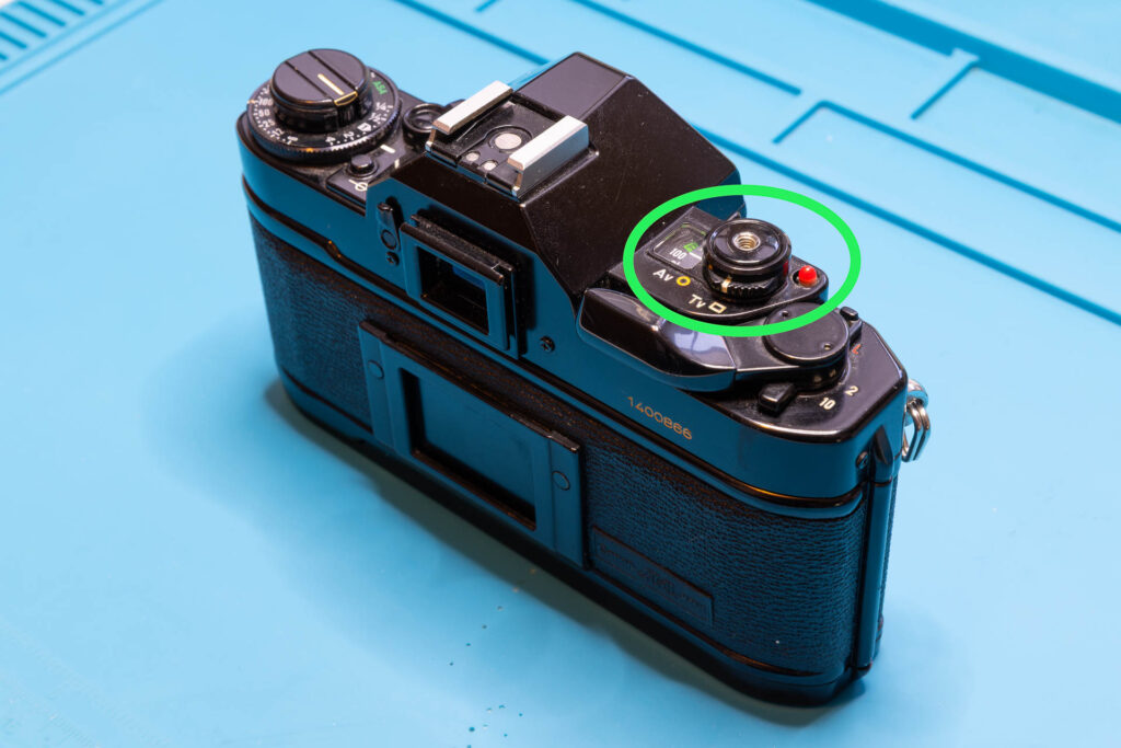
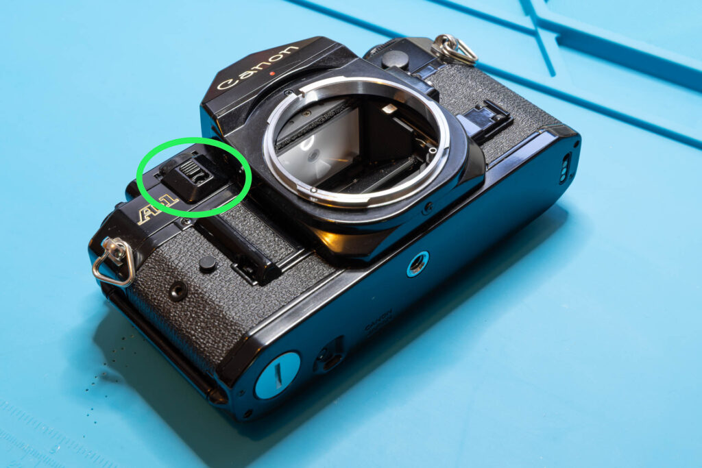
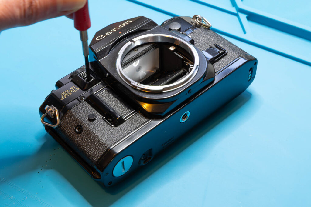
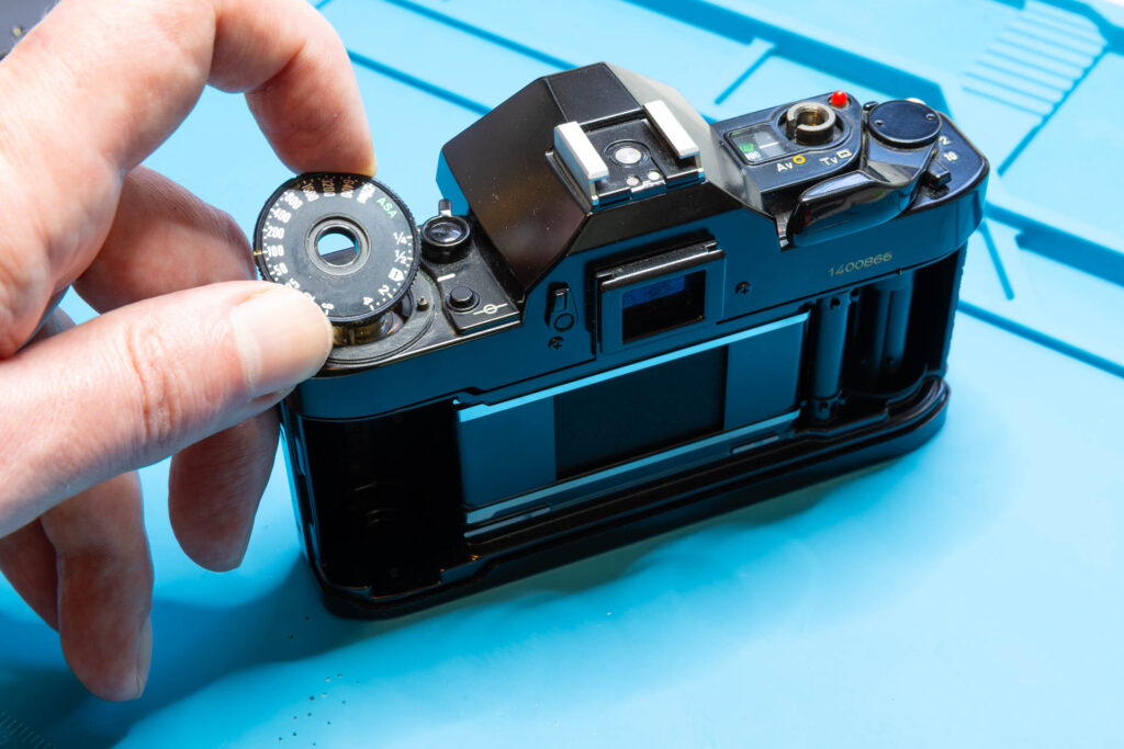
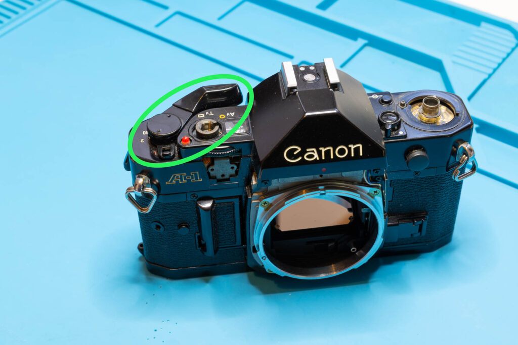
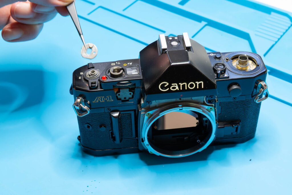
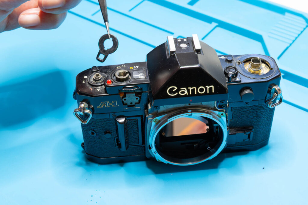
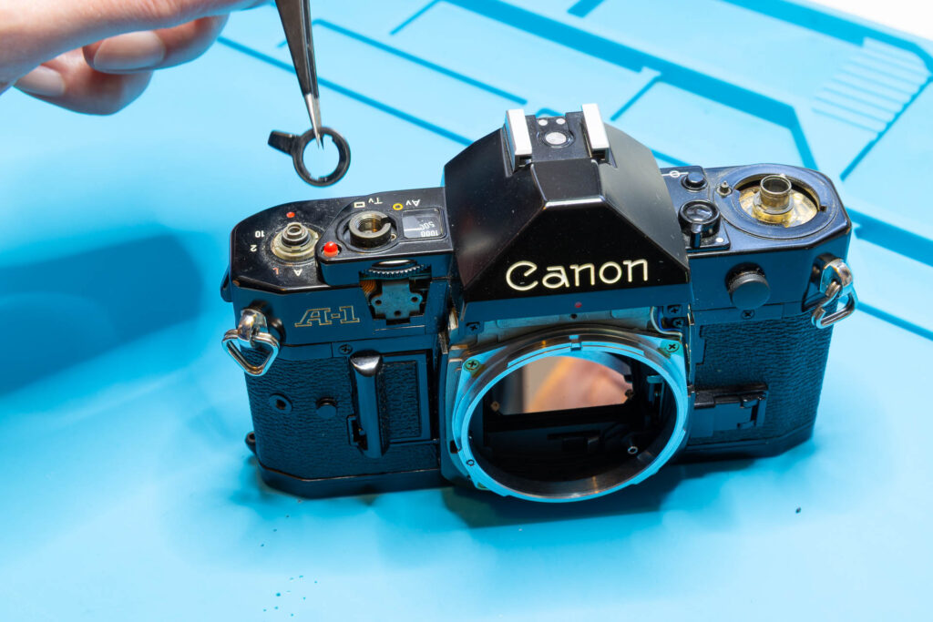
Step 1: Remove the Release Button
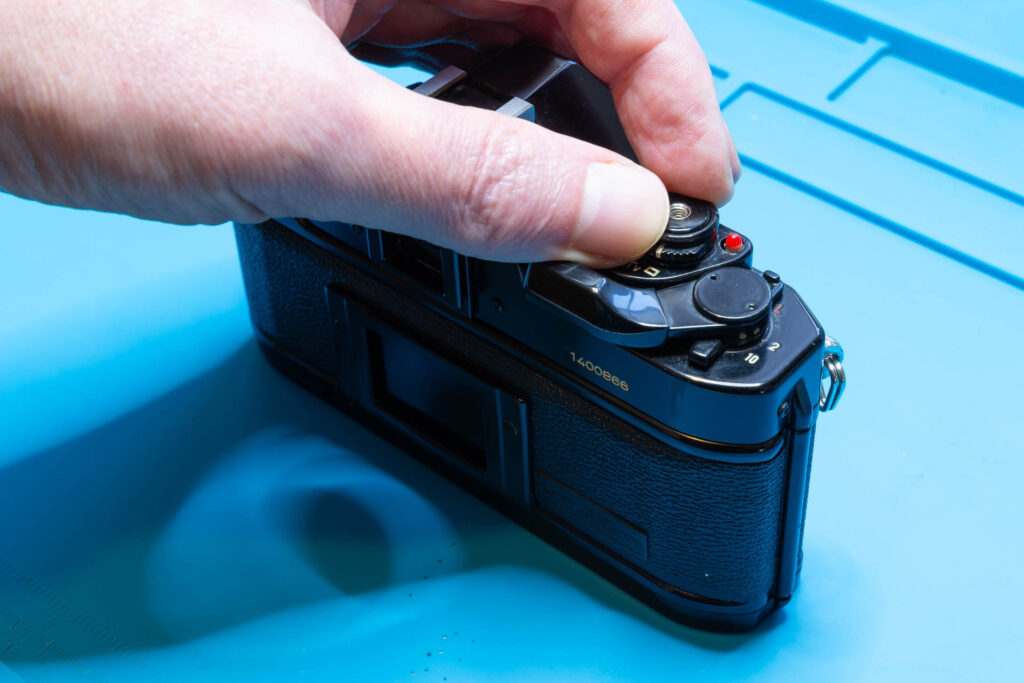
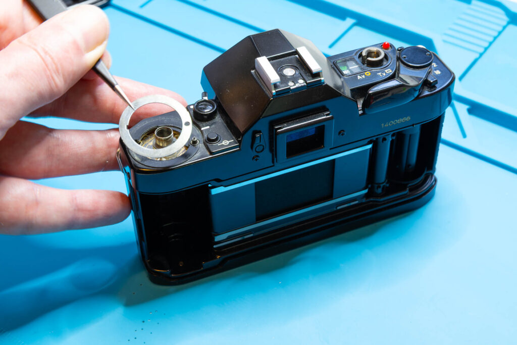
Often, removing the release button is a bit tricky. If you are very lucky you can unscrew its retaining ring with your bare fingers. However, more often than not the retaining ring is stuck and considerable force is needed to unscrew it. In this case, I would not suggest to spill any liquids, like isopropanol, oil, or, WD-40, into the camera to unstuck the ring. The liquid might go anywhere inside the camera, doing more harm than good. Instead, I suggest to use pliers with smooth, parallel-set jaws (like a Knipex 86-05-150) and a rubber cloth for increased grip and scratch protection. The retaining ring is unscrewed in counter-clockwise direction.
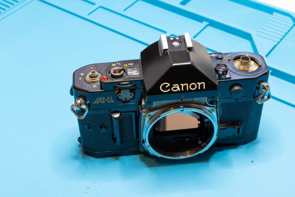
Since you cannot remove the top cover without removing the release button I put this as first step. If you cannot unscrew its (probably stuck) retaining ring it does not make sense to continue with the other steps. In this case, the help of a professional camera repairer is highly recommended.
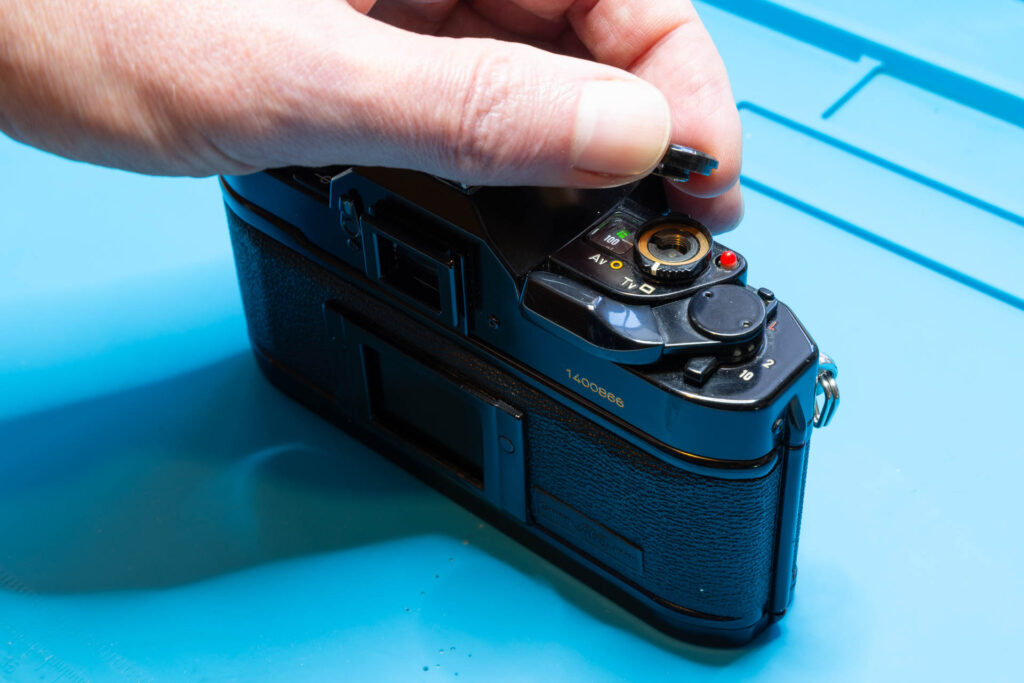
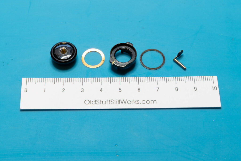
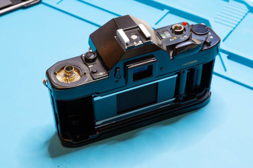
After this step, the following parts are removed (in removal order from left to right): the release button with retaining ring (cannot be separated), washer #1, the AE mode selector, washer #2, and the pin of the release button.
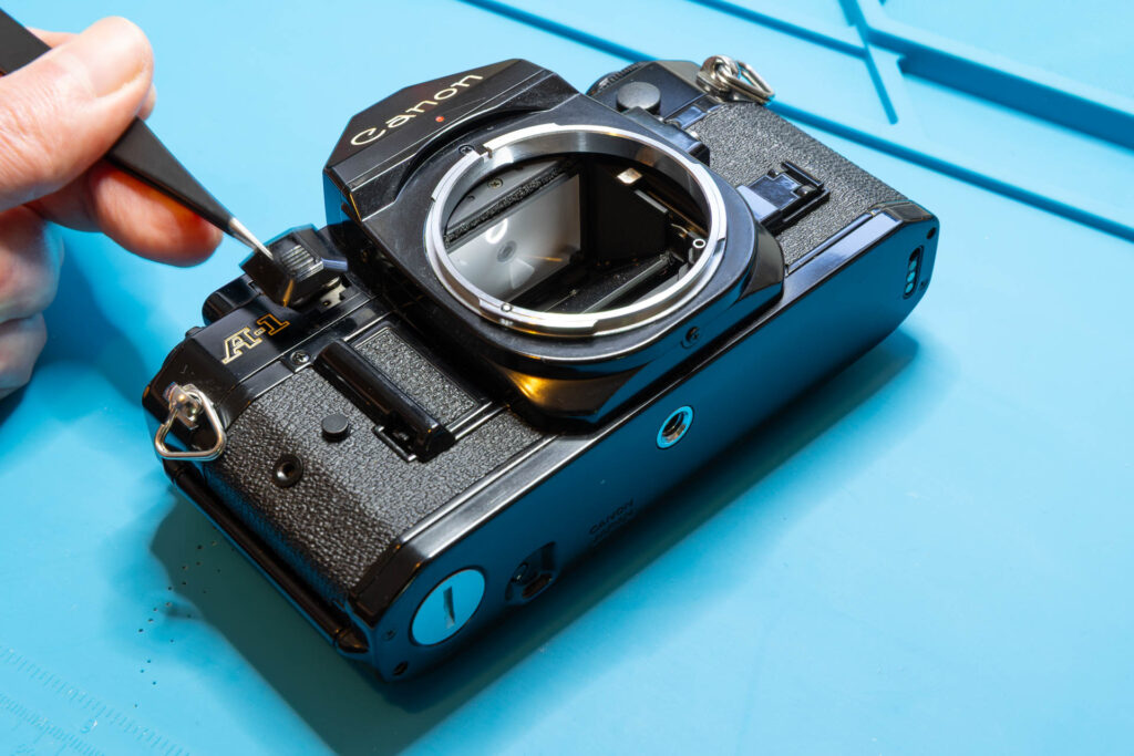
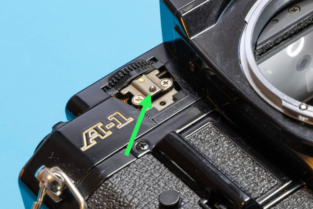
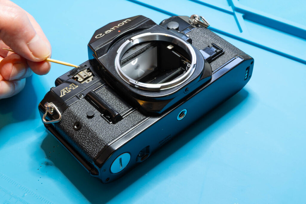
Step 2: Remove the AT Dial Guard
Removing the AT dial guard is straightforward. It only requires the removal of three screws. The first screw is only accessible if you slide the AT dial guard upwards. Attention: The guard mechanism contains a tiny steel ball that can easily get lost. To reduce the danger of the steel ball falling into the camera (or disappearing in Nirvana) I do not grab it with tweezers but use a toothpick with a tiny amount of grease at its tip. If you still lose the steel ball (or a previous “repairer” already lost it): It’s diameter is 1.57mm (1/16″), it can be purchased easily (look for “steel bearing ball”).
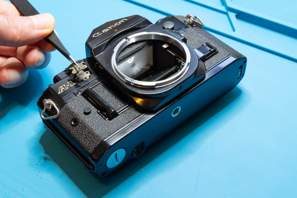
After this step, the following parts are removed (in removal order from left to right): plastic frame and slider of the AT dial guard, one screw (1.65×2.3mm), steel ball (1.57mm), steel base plate (two parts), two countersunk screws (1.60×1.4mm).
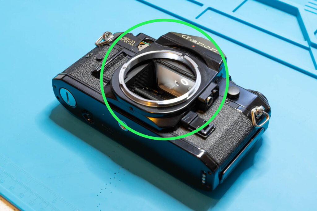
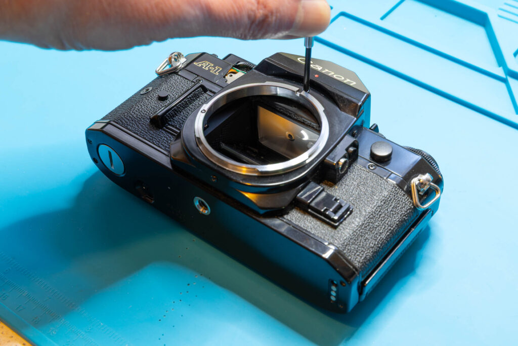
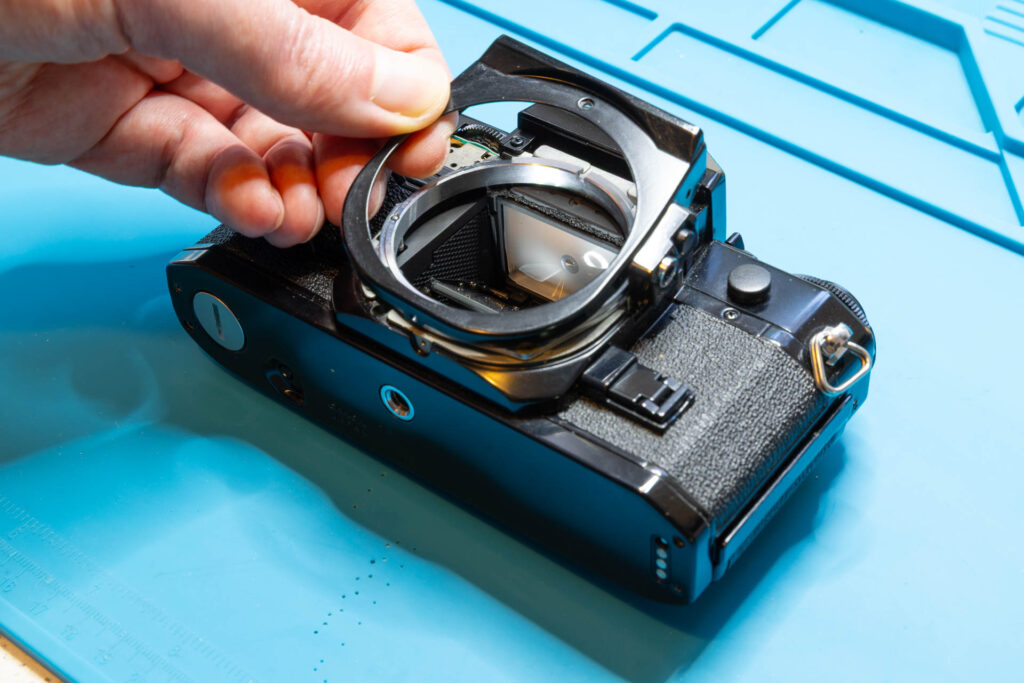
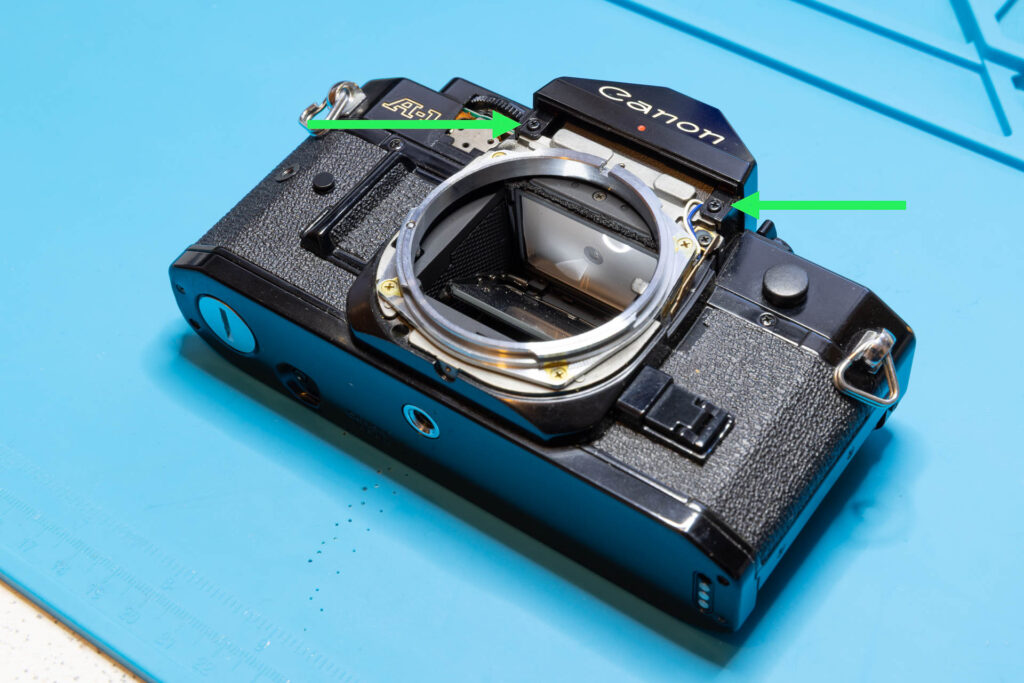
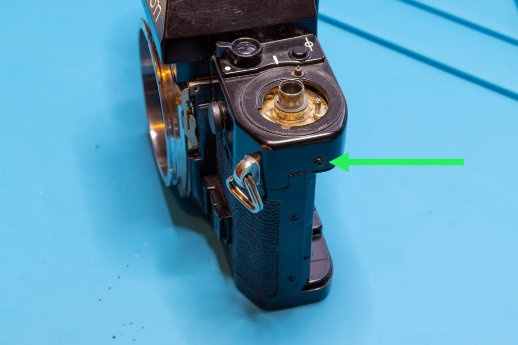
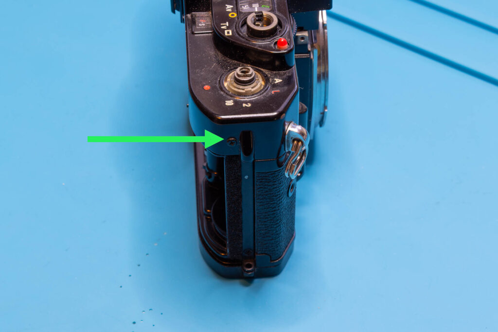
Step 3: Remove the Front Cover
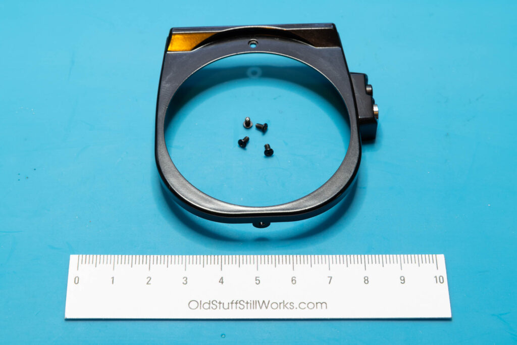
The front cover (the black frame around the lens mount) is held by four screws: one at the front, one each at the left/right side, one at the bottom. After unscrewing them, a bit of wiggeling might be necessary to loosen the front cover. The small plastic housing for the exposure preview/memory switches at the right side will come off together with the front cover. If necessary it can be separated from the front cover by sliding it backwards.
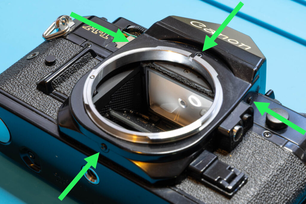
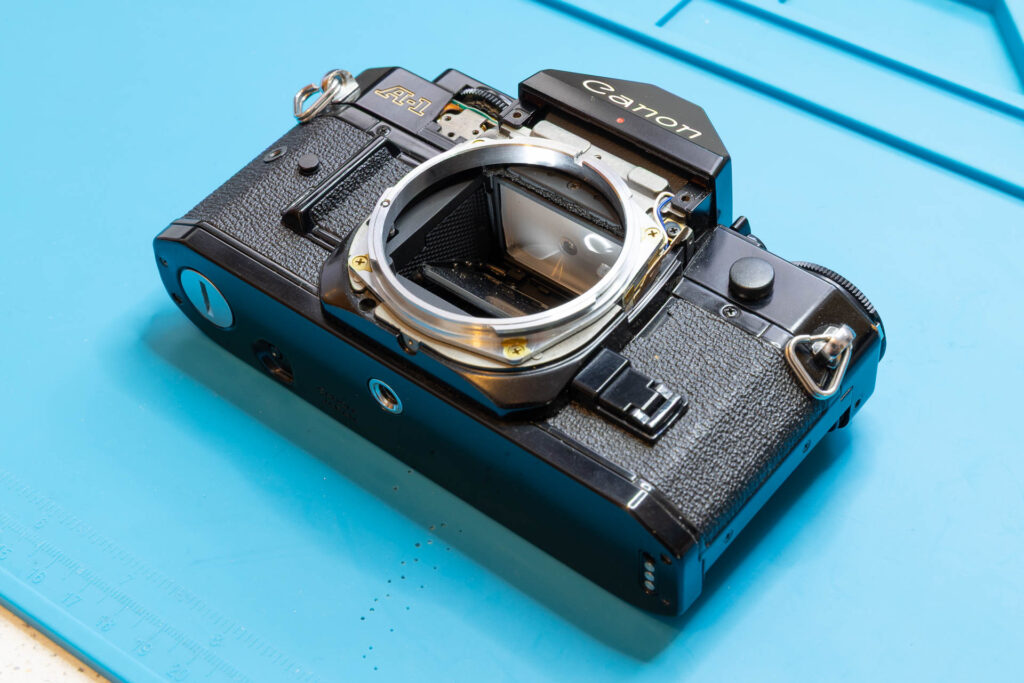
After this step, the following parts are removed : front cover, four screws (1.65×2.6mm).
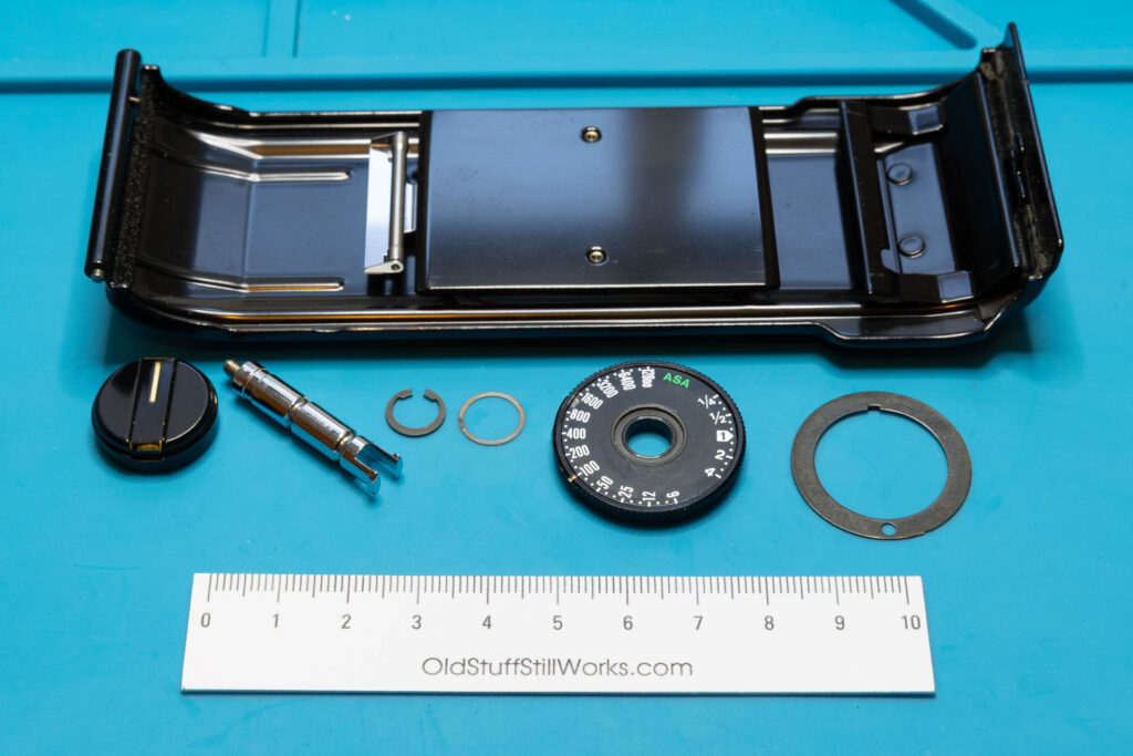
Step 4: Remove the Rewind Knob and ASA Film Speed Dial
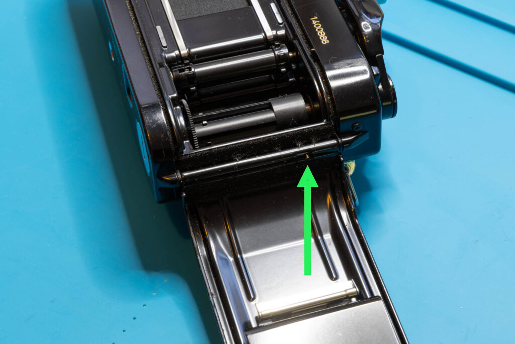
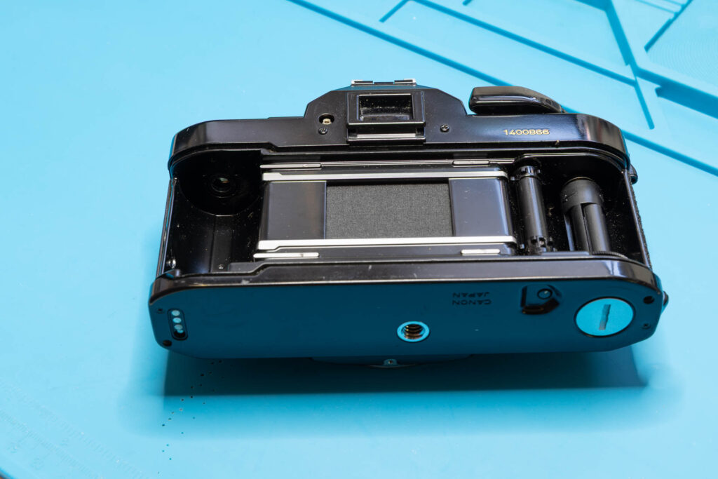
First of all, pull up the rewind knob to open the back cover (“film door”). From now on, be careful to not touch the shutter curtain. It’s a good idea to remove the back cover now by pulling the hinge on its inner-left side downwards. After you have removed the rewind knob and shaft and you close the back cover accidentally, it would be very hard to open it again since there is no alternative opening mechanism. In the picture series below, I removed the back cover only after removing the rewind shaft (that was a bit late).
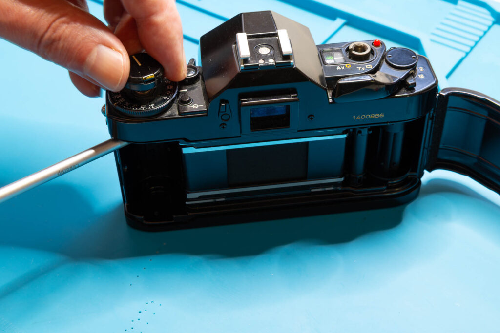
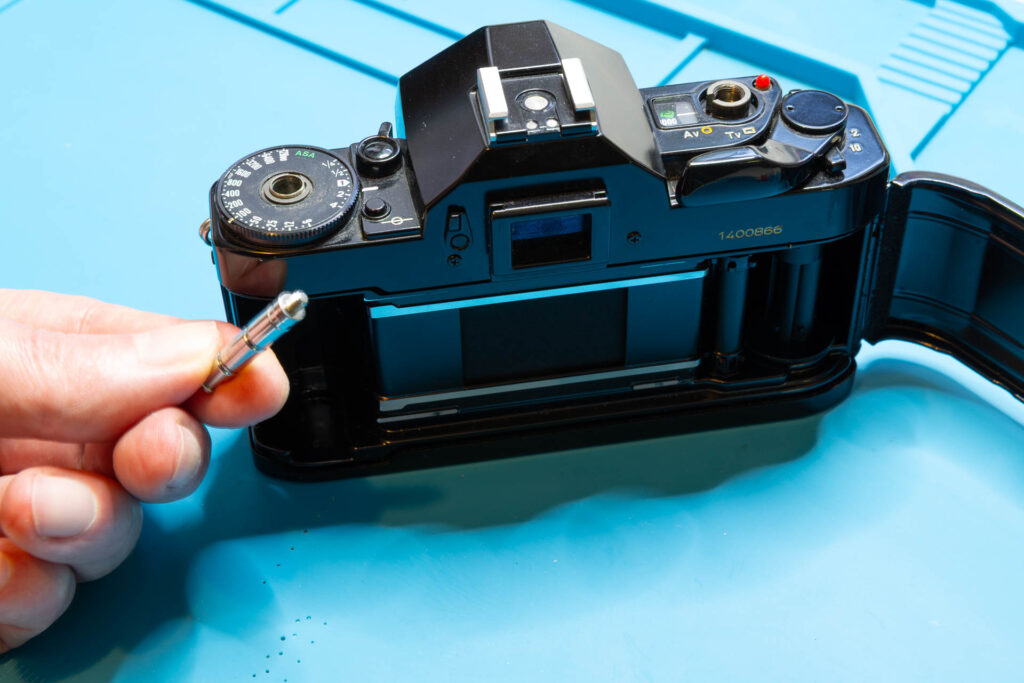
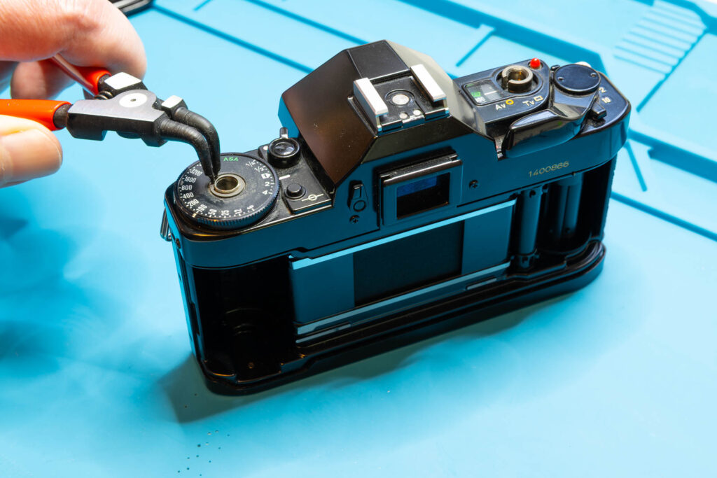
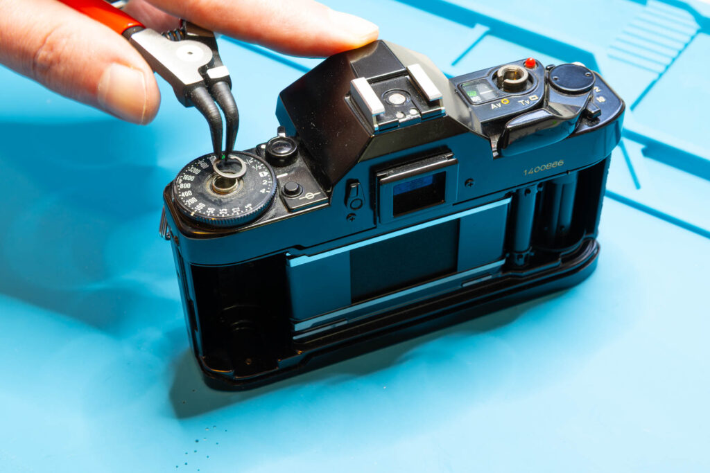
Push the rewind knob in again but not completely (there is a latching “middle” position). Counter the lower, slotted end of the rewind shaft with a flathead screwdriver or pliers. Unscrew the rewind knob in counter-clockwise direction. Then, push/pull the rewind shaft down into the film chamber.
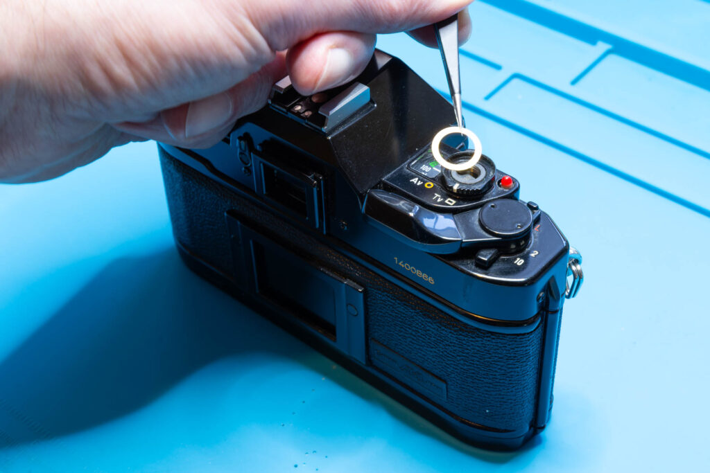
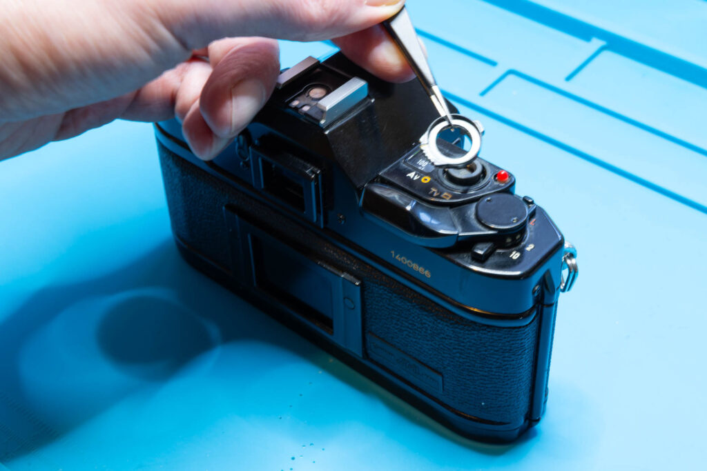
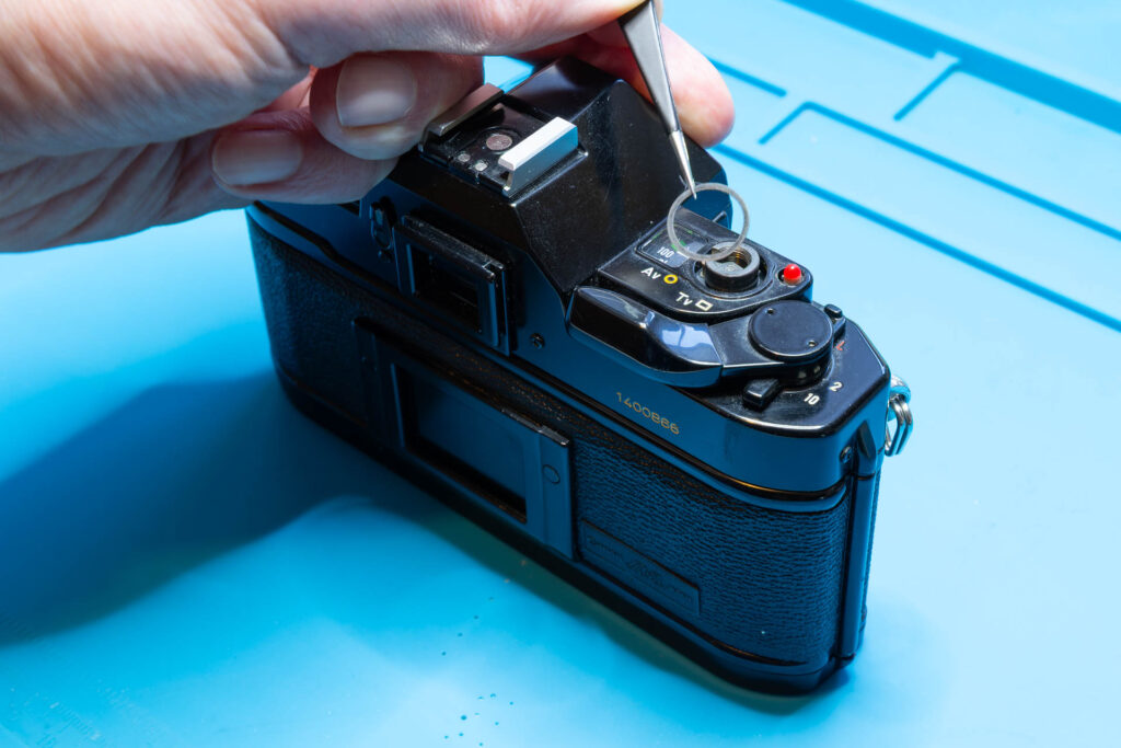
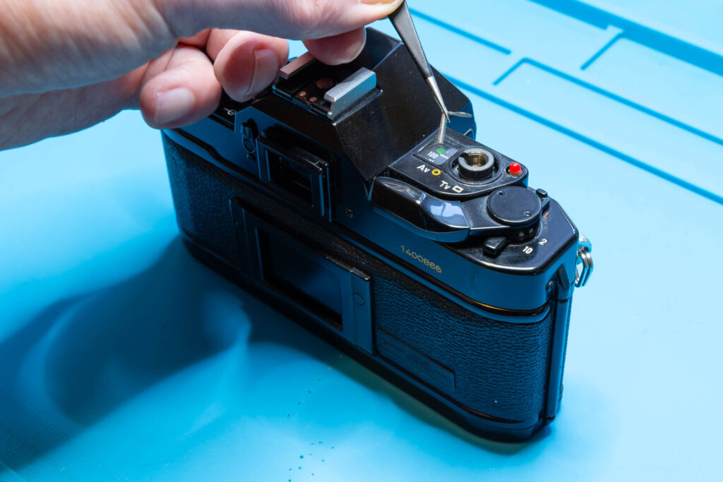
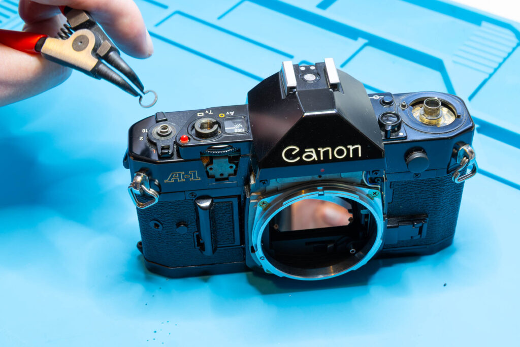
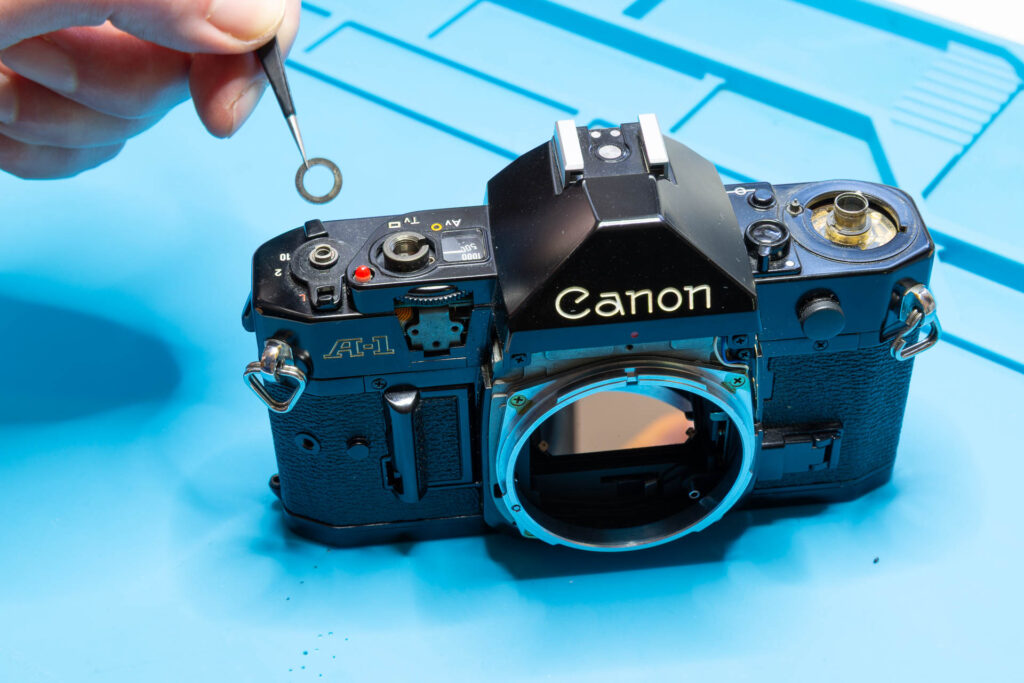
Remove the snap ring securing the ASA film speed dial. For this, the best tool is a circlip / snap ring pliers for small rings, like a Knipex 46-21-A01. Next, remove the small washer. Then, you can lift off the ASA film speed dial. Finally, remove the round spacer.
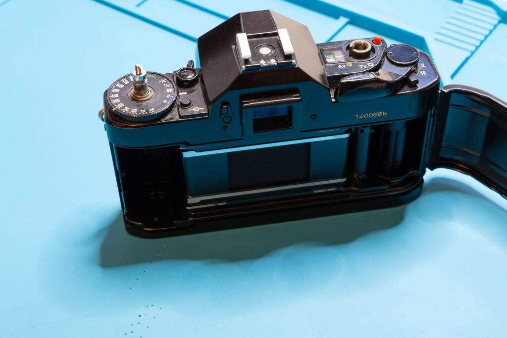
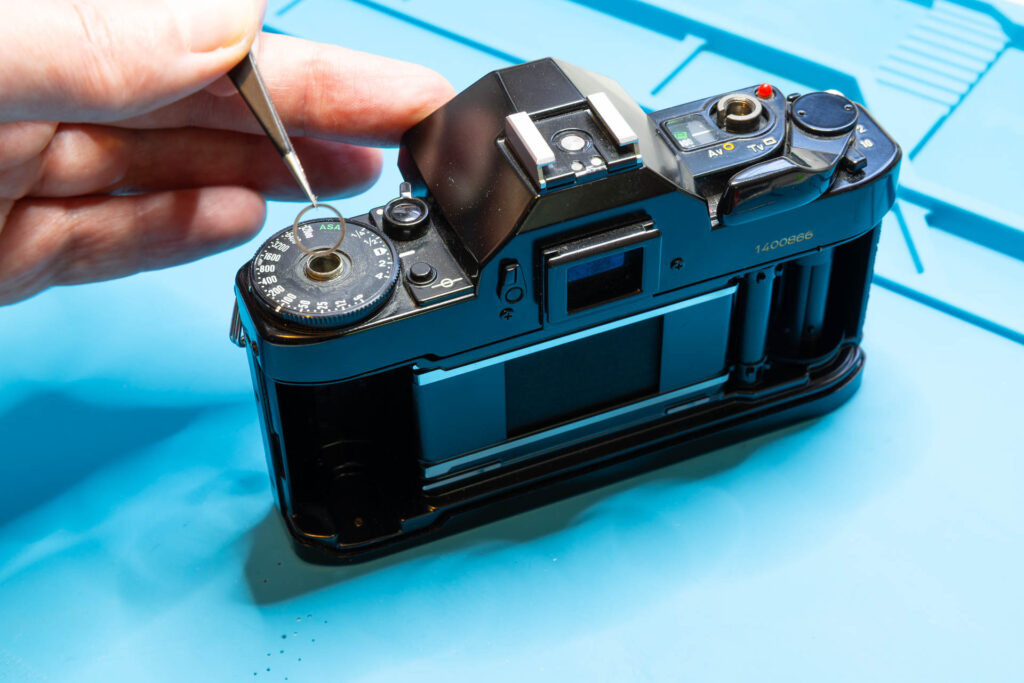
After this step, the following parts are removed (in removal order from left to right): back cover, rewind knob, rewind shaft, snap ring, washer, ASA film speed dial, spacer.
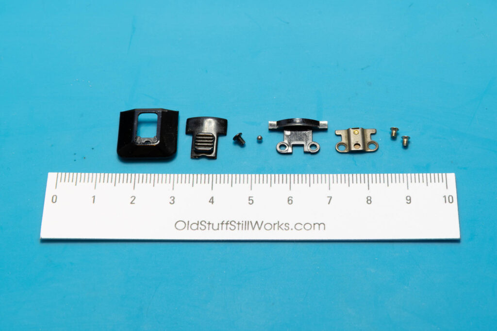
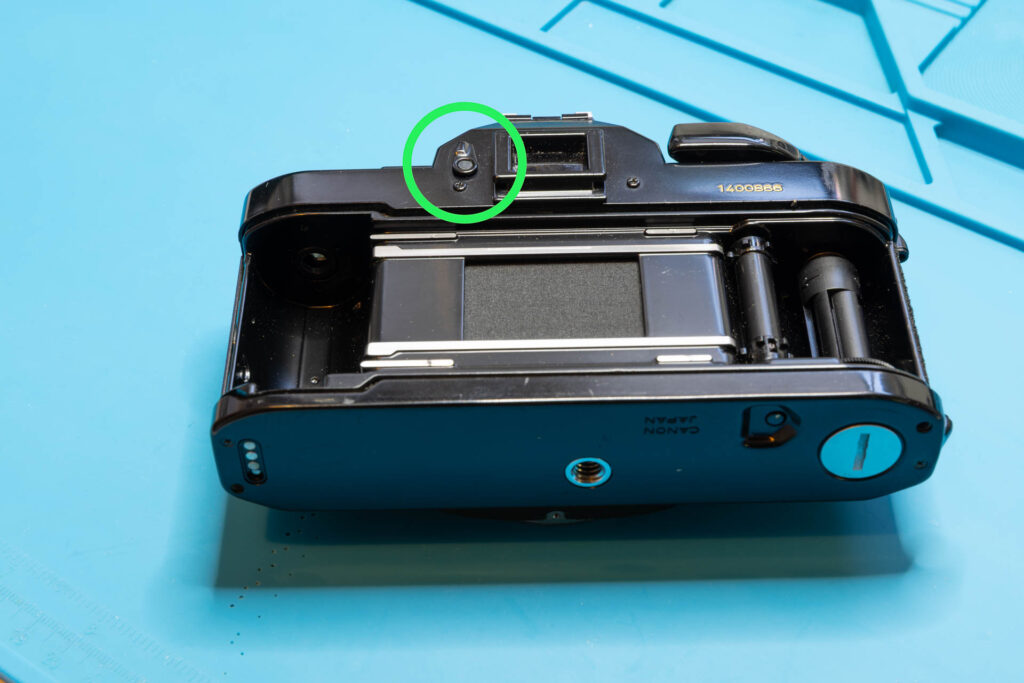
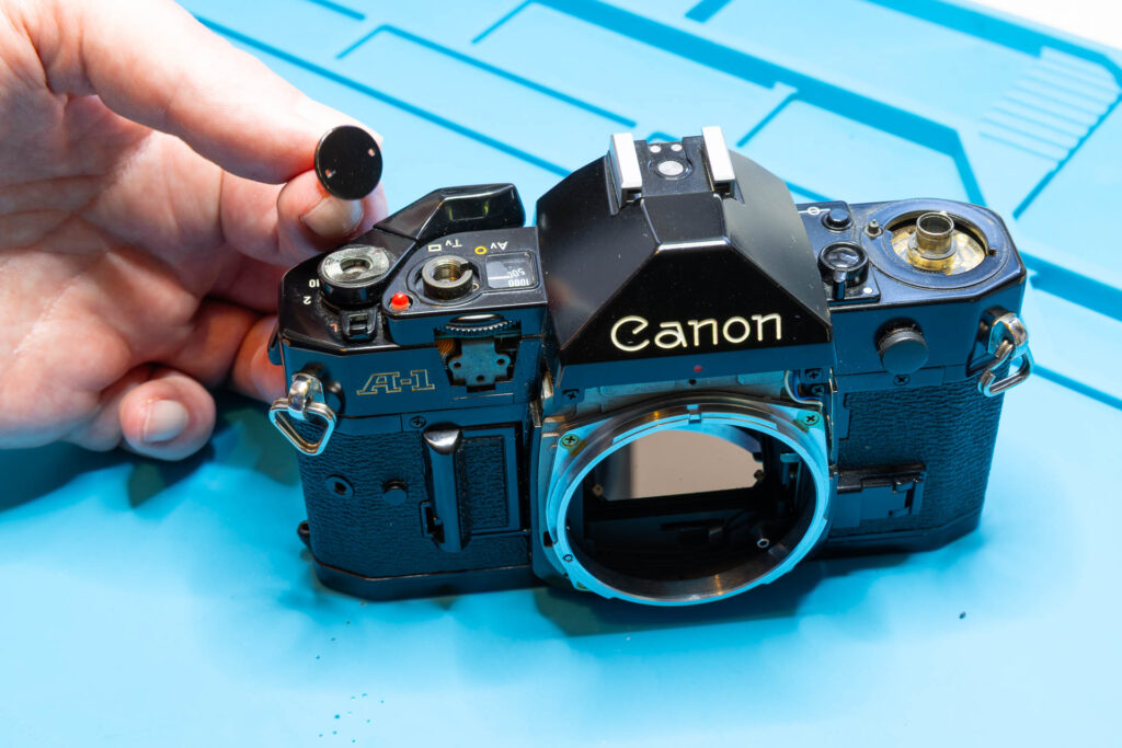
Step 5: Remove the Eyepiece Shutter Lever
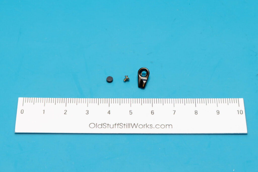
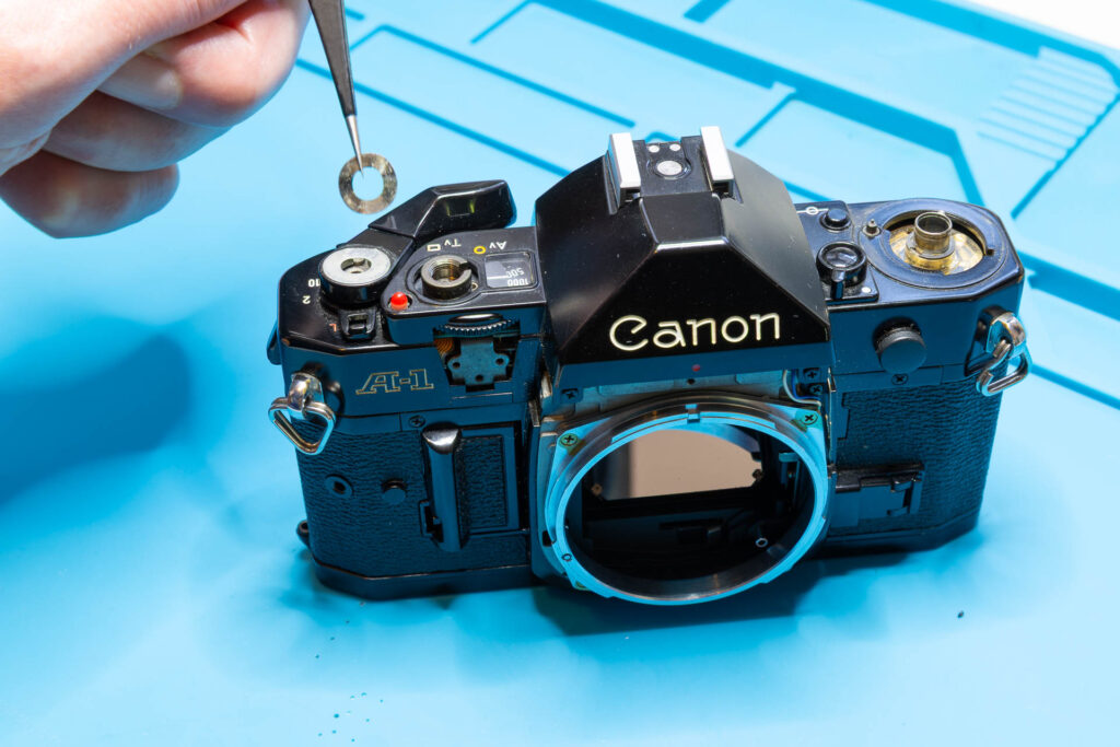
First, remove the round rubber patch from the lever that covers the screw. You can try to do this with tweezers with sharp points. Often, the patch comes off easily since the glue is already degraded. If not, you can put a small drop of isopropanol around the patch to soften the glue. After you removed the patch, you can unscrew the lever and lift it off.
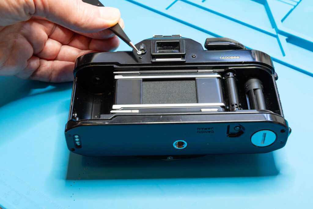
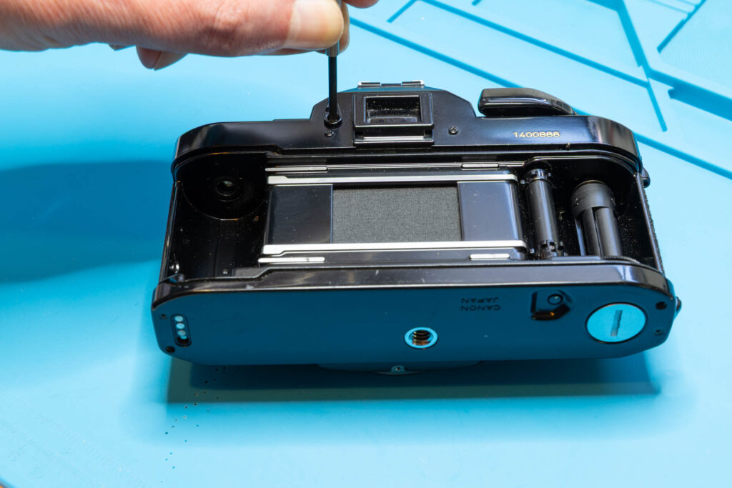
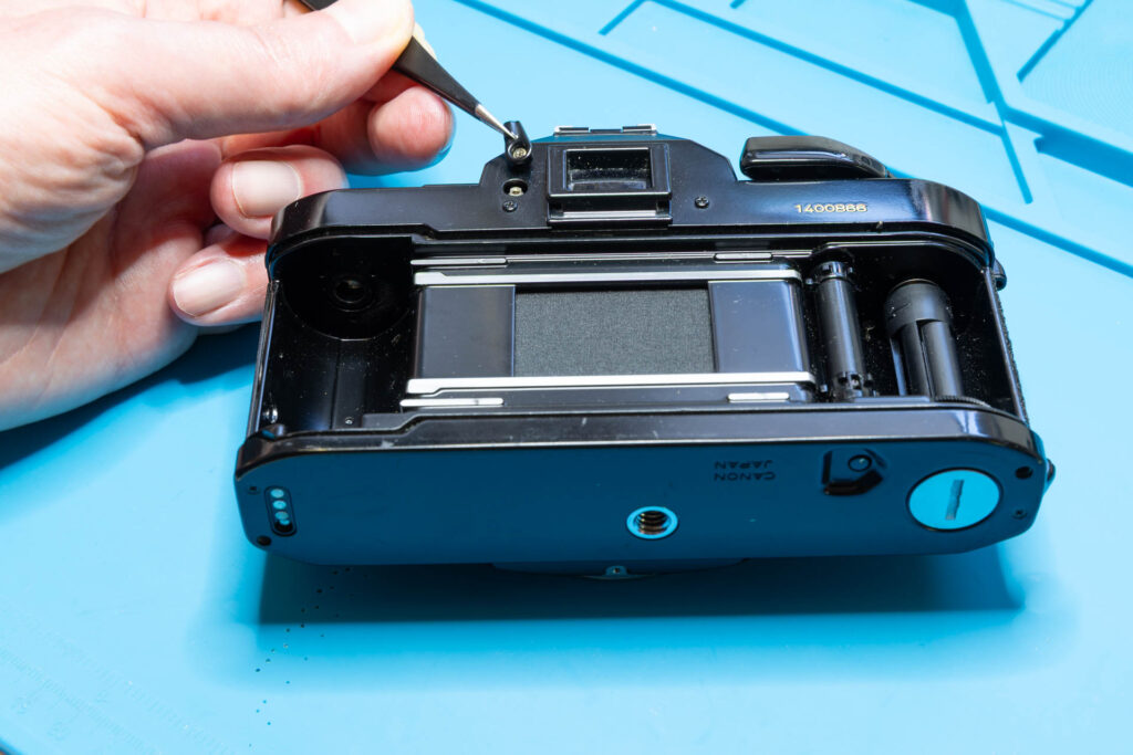
After this step, the following parts are removed (in removal order from left to right): rubber patch, screw (1.35×1.8mm), eyepiece shutter lever.
Step 6: Remove the Film Advance / Main Switch / Multiple Exposure Levers
First, remove the screw that secures the film advance lever (also called “winding lever”). Unscrew it in counter-clockwise direction. This is the only tricky part of this step since the painted screw surface can be scratched easily. This type of screw is sometimes called 2-hole, “snake eye” or “pig’s nose”. In the screw head, there are two bores, each with a diameter of about 0.9mm and 9.8mm apart. To unscrew it, you will need a tool with two small (preferably round) tips, like a larger pair of tweezers, compasses, lens spanner, or the like. If the screw is not too tight, even a rubber plug may work. For this task, I always use the same Knipex pliers I also use for the snap rings.
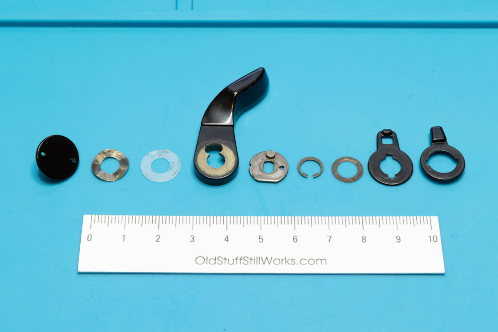
After removal of the screw, you can just lift off the film advance lever, two washers (first: metal, second: teflon) and the winding seat. Afterwards, remove the snap ring securing the main switch lever. Then, you can lift off another washer, the main switch lever, and the multiple exposure lever.
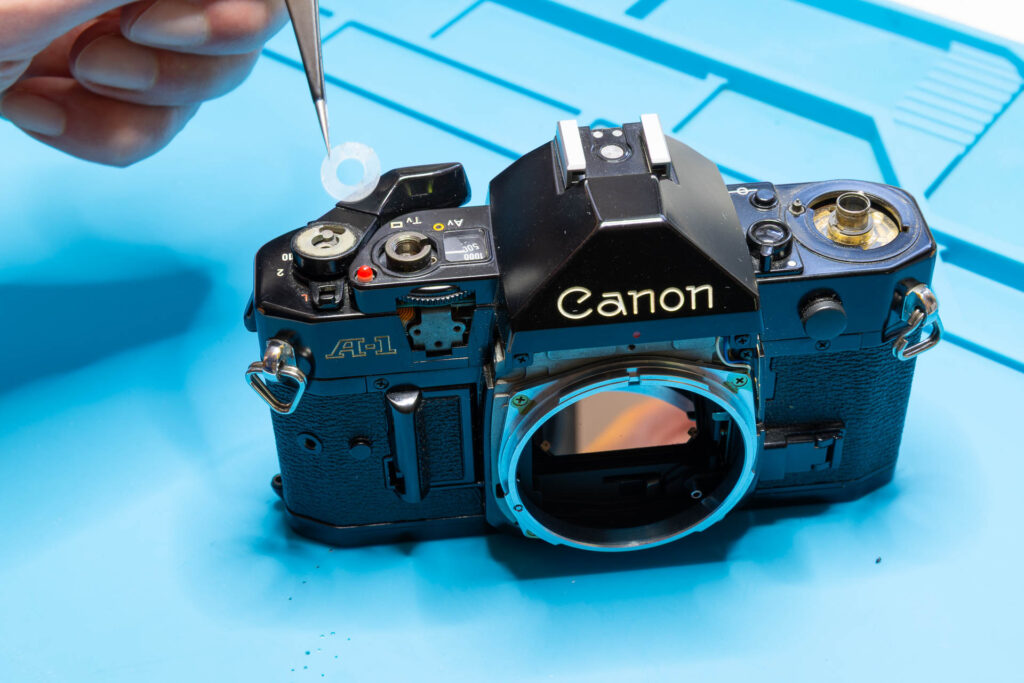
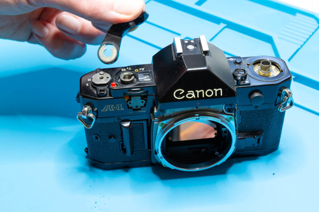
After this step, the following parts are removed (in removal order from left to right): film advance lever screw, washer #1, washer #2 (teflon), film advance lever, winding seat, snap ring, washer #3, main switch lever, and multiple exposure lever.
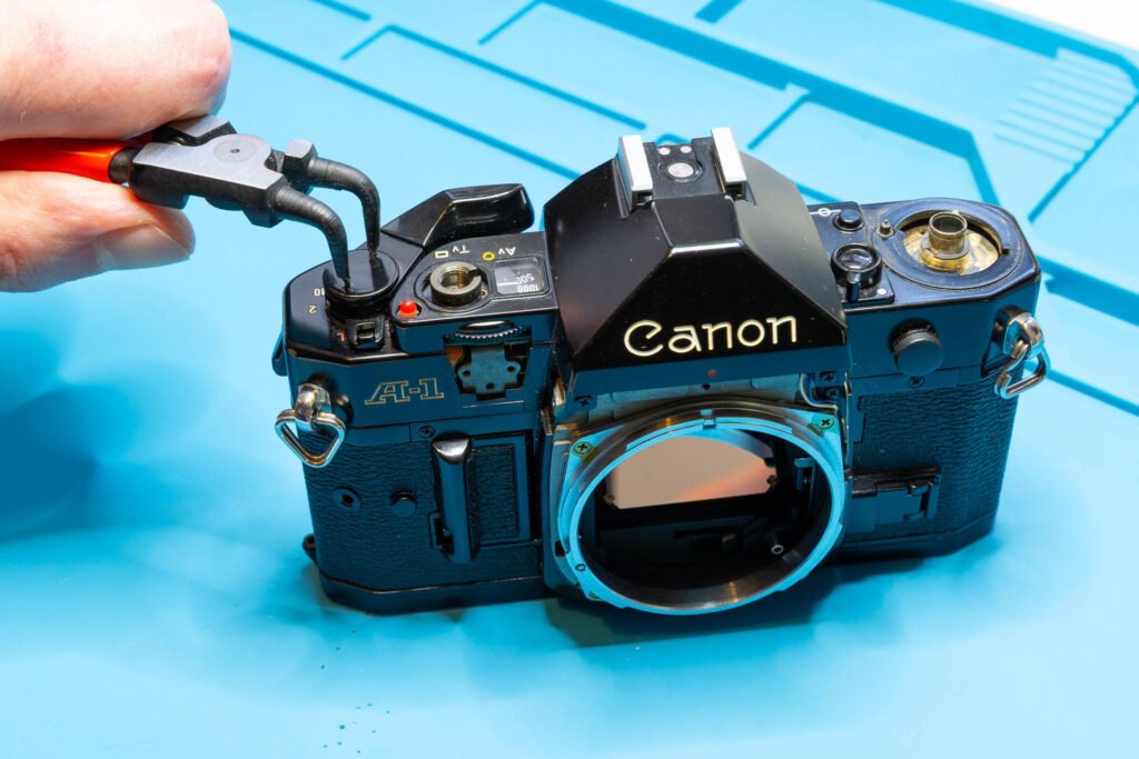
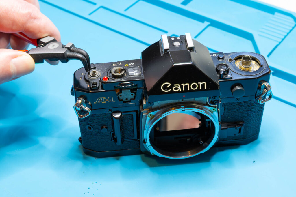
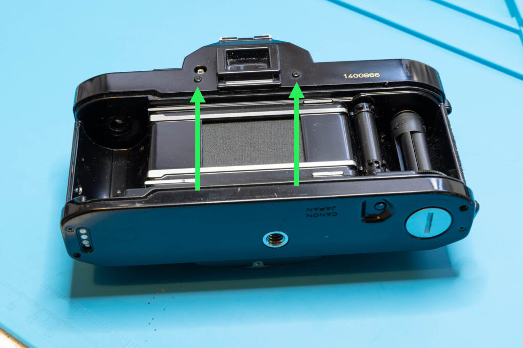
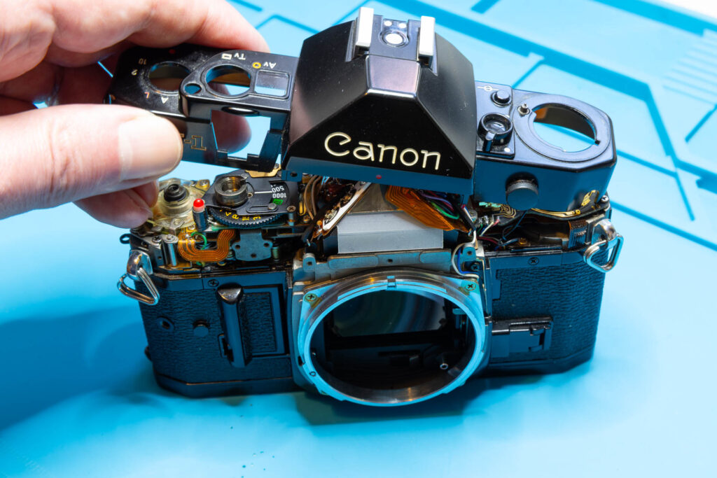
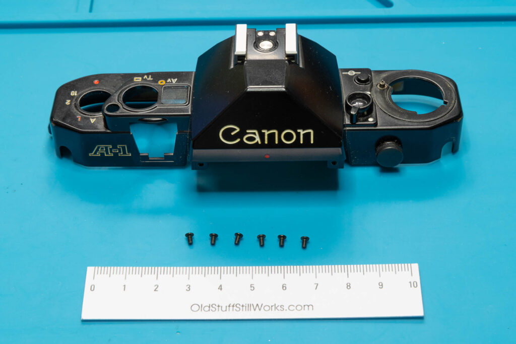
Step 7: Remove the Top Cover
The top cover is secured by six screws; two at the front, one each at the left/right side, two at the back of the camera. Remove these screws. Then, start lifting off the top cover gently, considering the following:
- The battery check LED may still cling to the top cover. If you notice this, gently press the LED down when lifting the cover.
- You have to wiggle and tilt the top cover a bit when lifting it off. The AT dial sticks out a bit through a cutout in the top cover, keeping the cover from lifting straight up.
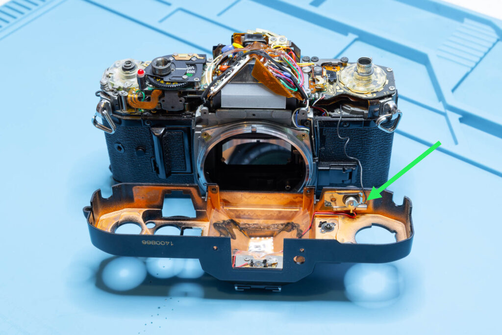
- The top cover is still connected to the main chassis by the black flash sync wire. The wire has a bit of slack so that you can lift off the cover and put it down in front of the camera.
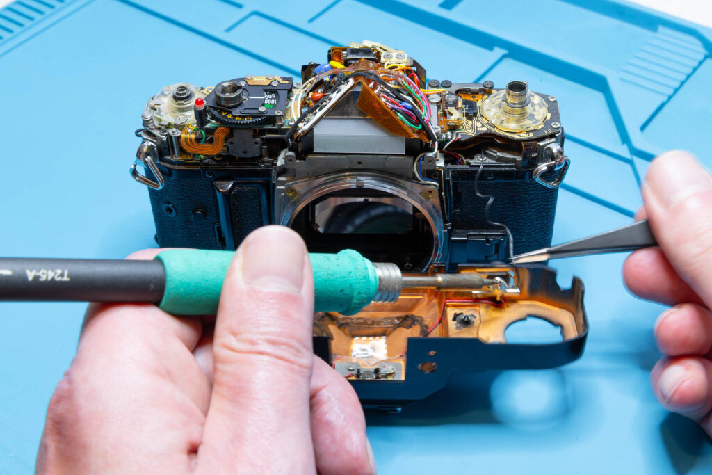
If you just want to inspect and, maybe clean, the switches and contacts or the eyepiece it might not be necessary to desolder the flash sync wire. However, if you want to perform a more complex maintenance or repair (like removing the mirror box) I strongly suggest to desolder it and put the top cover to the side. Otherwise, handling the camera can get much more difficult, you could scratch the camera or the top cover, or the flash sync wire could tear off.
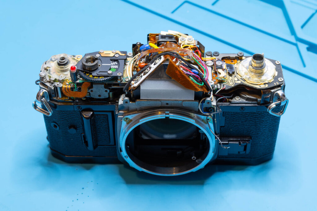
After this step, the following parts are removed: six screws (1.65×2.8mm), top cover.
That’s all.