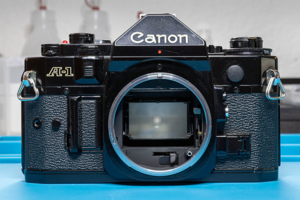
Disclaimer: The repair procedure I present in this post is inspired by the official service manual and renowned repair articles but mainly reflects my own experience. The description may be incomplete and might even contain errors. Consider that I am just a self-taught hobbyist, not a trained professional. Copy this procedure at your own risk! Also, consider that any attempt to disassemble and repair a camera carries a certain risk to worsen its condition or to even breaking it completely.
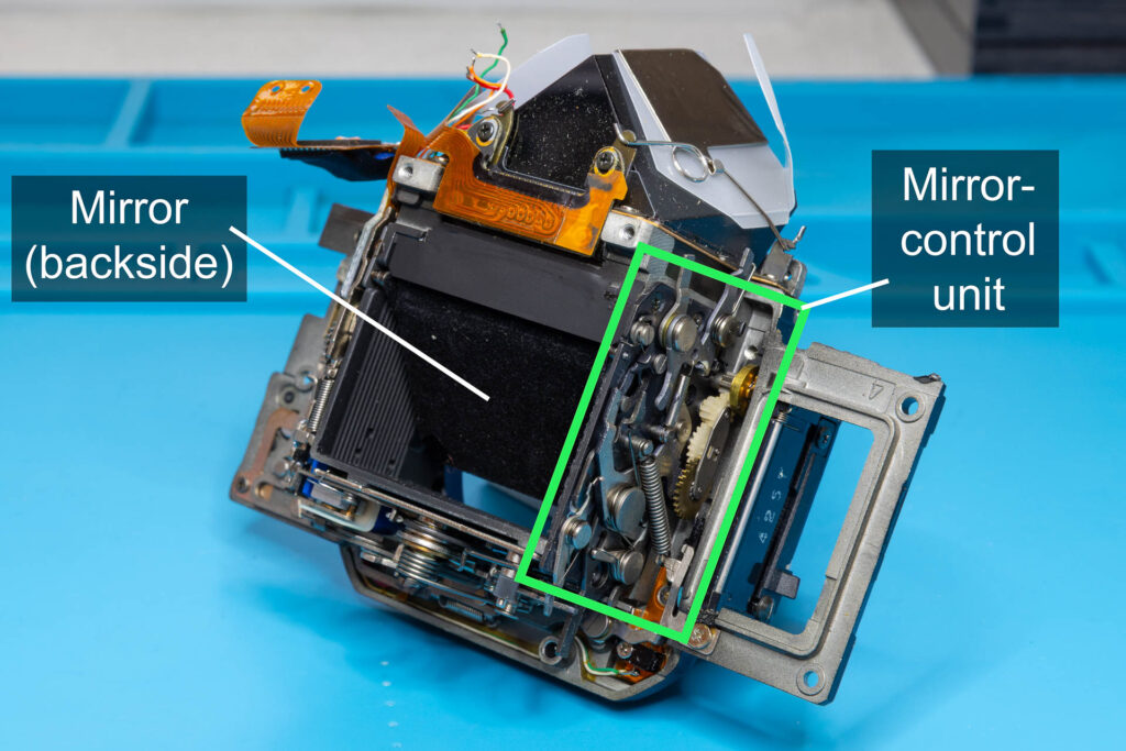
Due to damage, you might have to replace the mirror-control unit and/or the mirror of a Canon A-1. Since removal of the mirror-control unit also removes the mirror I cover both components in one post. In this post, I present the disassembly and reassembly steps that are necessary in the order that works best for me.
Why Do Both Components Come Off at the Same Time?
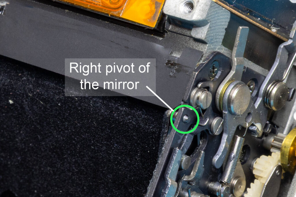
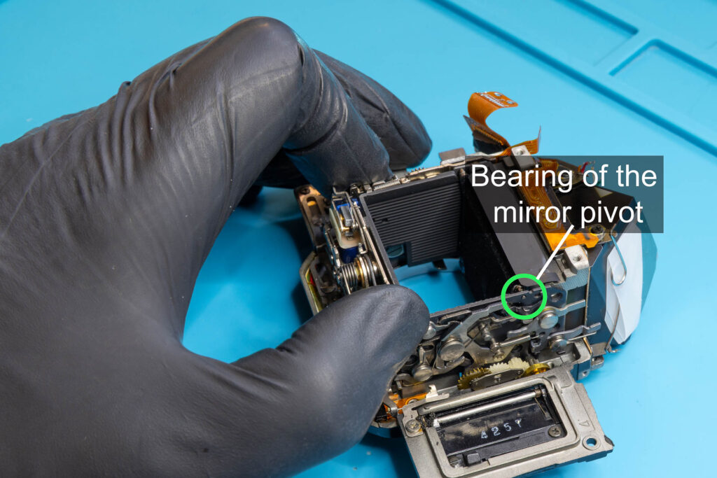
The reason why both the mirror-control unit and the mirror come off at the same time during disassembly is the following: The right pivot of the mirror (seen from the backside) rotates in a journal bearing of the mirror-control unit. That is, if you want to remove the mirror, you have to remove the mirror-control unit. Even if you just want to remove the mirror-control unit, you can’t prevent the mirror from coming off.
Preparation
First, follow the procedure described in this blog post to remove the top cover of the camera.
Then, follow the procedure described in this blog post to remove the mirror box of the camera.
Tools
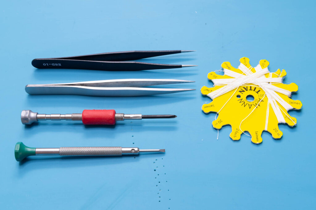
To replace the mirror-control unit and/or the mirror of a Canon A-1, you need a certain set of tools. These are my recommendations:
- tweezers with sharp points
- JST screwdriver #00
(A Phillips screwdriver PH00 or PH0 might work “somehow” but be aware that it might damage the screw head.) - flat-head screwdriver ~2mm
- strong sewing yarn
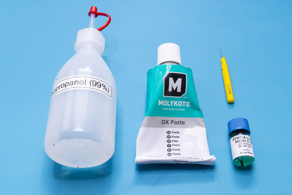
If you also want to clean and lubricate the mirror-control unit, I recommend the following tools and materials:
- isopropyl alcohol (IPA)
- grease
You should use a mineral / synthetic, acid-free grease that is suitable for moving steel parts. Personally, I use Molykote DX Paste. - oil
You should use a mineral / synthetic, acid-free oil with low to medium viscosity. It must not dissolve brass or the elements it consists of (copper, zinc). Doesn’t need to be expensive, good quality sewing machine oil is fine. Personally, I use Moebius 9010 watch oil but just because I have it anyway. - oiler for watchmakers (or similar, small tool to apply oil and grease)
Step 1: Remove the Mirror-Return Spring
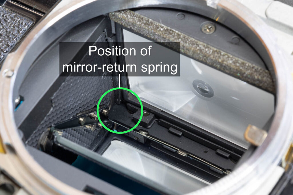
The mirror-return spring is a little torsion spring in the upper left corner of the mirror box (seen from the front) that pushes the mirror down to its resting (45°) position. To achieve this, its shorter, straight leg presses against the frame of the mirror box and its longer, hooked leg presses against a pin on the side of the mirror unit. The spring sits on a screw pin under the mirror-control unit.
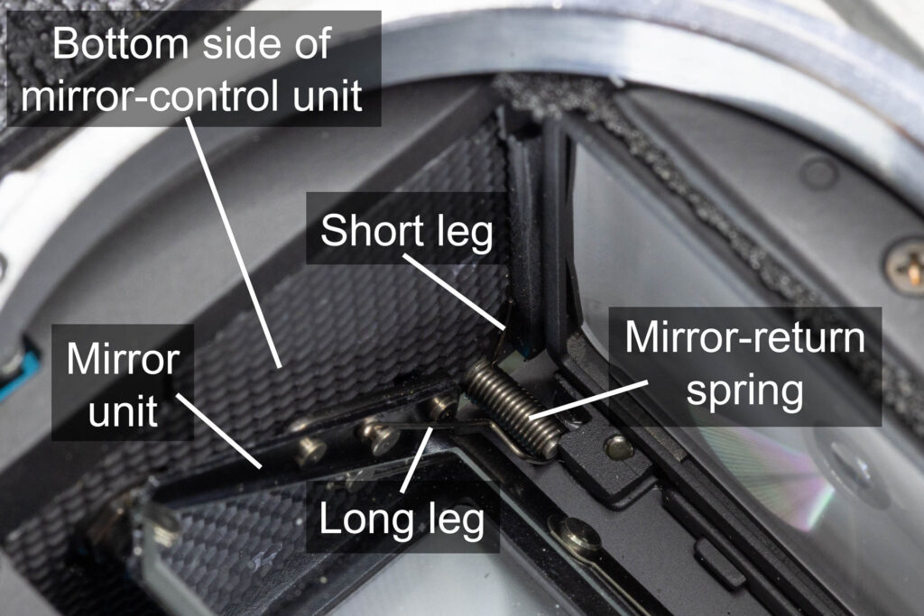
Removing the mirror-return spring is the most tricky part of the disassembly. There is an official way to do it and an alternative way that I use:
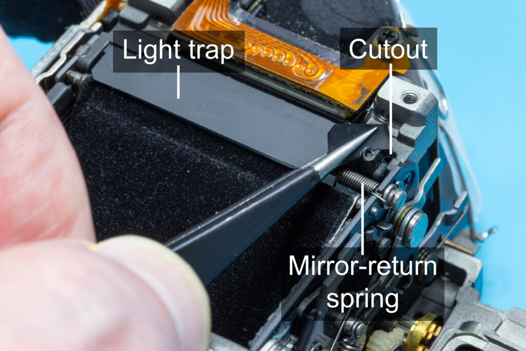
The official way is to peel back the right side of the light trap (black metal foil) on the back of the mirror box to reveal the mirror-return spring and a vertical cutout above it. From the front of the mirror box, grab the short leg of the mirror-return spring with tweezers and push it through this cutout. Then, the mirror-return spring would be removed automatically when we remove the mirror-control unit in the next step. However, there is a catch to this approach: It never worked for me! In all Canon A-1s I disassembled, the cutout was almost completely blocked by the frame of the focus screen. Attempts to still push the leg of the spring through it resulted in bending the leg out of shape.
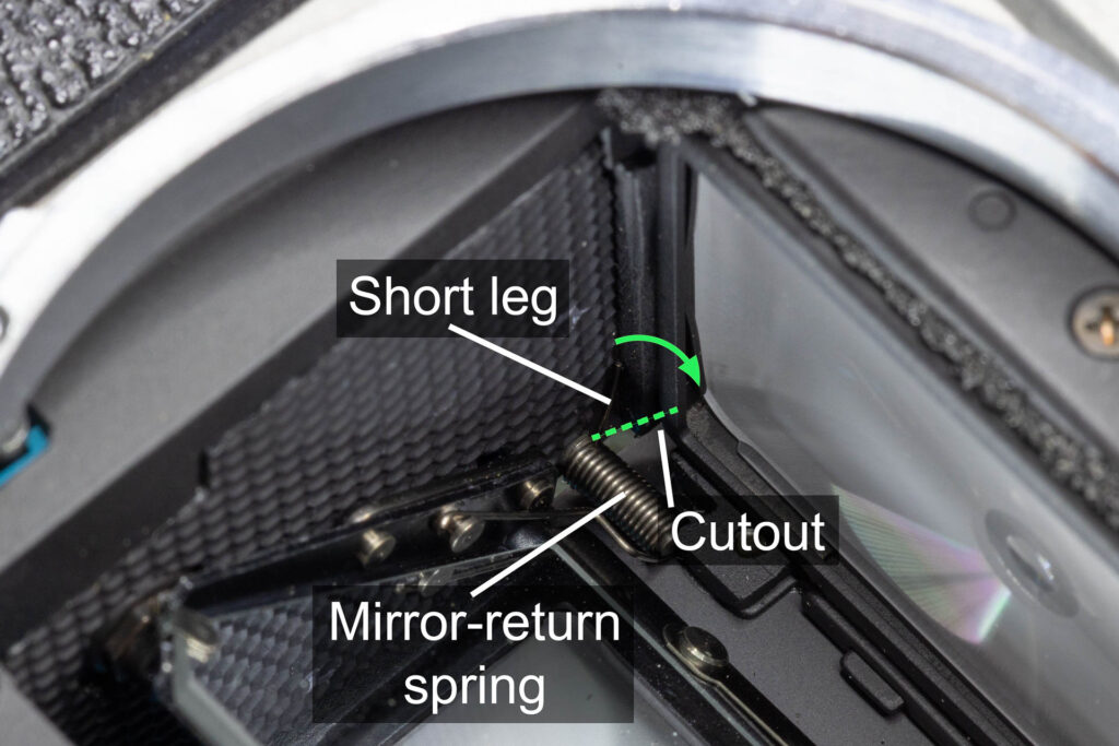
The alternative way to remove the mirror-return spring I use instead is simple: Just unscrew the screw pin on which the spring sits. Then, the spring will either fall out through the front of the mirror box or, if not, you can just grab it with tweezers and pull it out.
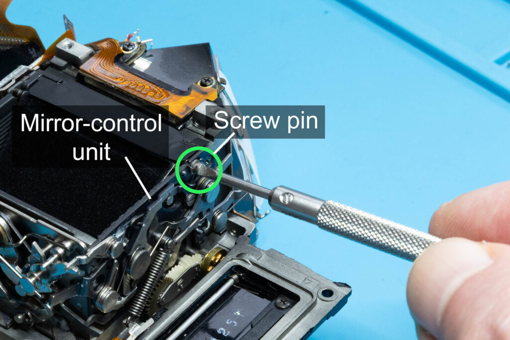
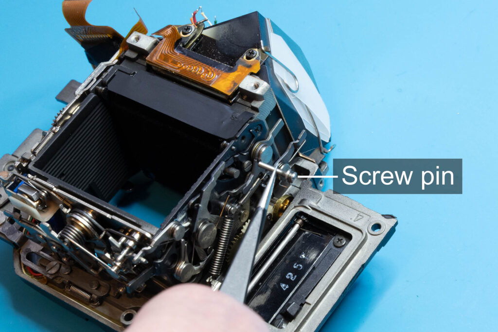
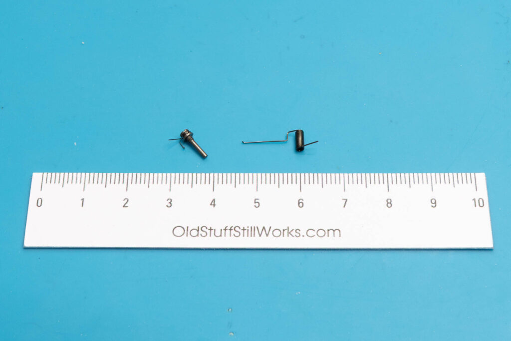
After this step, the following parts are removed (in removal order from left to right): screw pin (1.20×6.5mm), mirror-return spring.
Step 2: Remove the Mirror-Lifting Spring
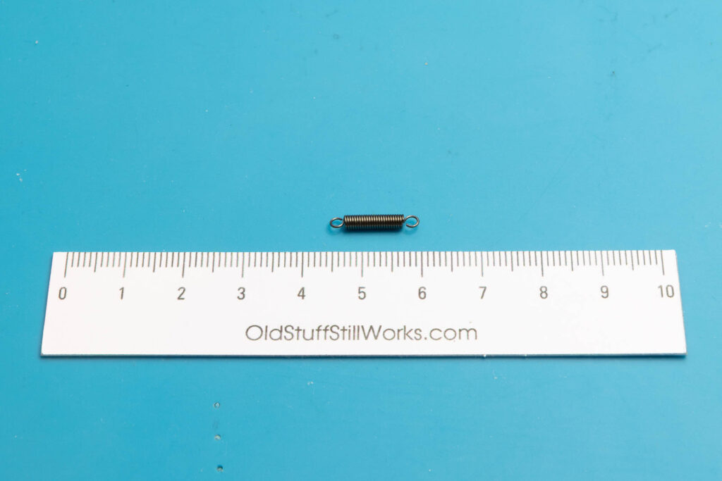
The mirror-lifting spring is a quite strong extension spring that connects the frame of the mirror box with the mirror-tensioning lever. Via mirror-tensioning lever and mirror-lifting lever, the spring forces the mirror to its upper position when a photo is taken. Use strong tweezers or a small screwdriver to remove this spring. First, remove its loop from the post on the mirror-tensioning lever. Then, remove its other loop from the hook on the frame of the mirror box.
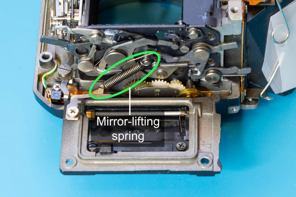
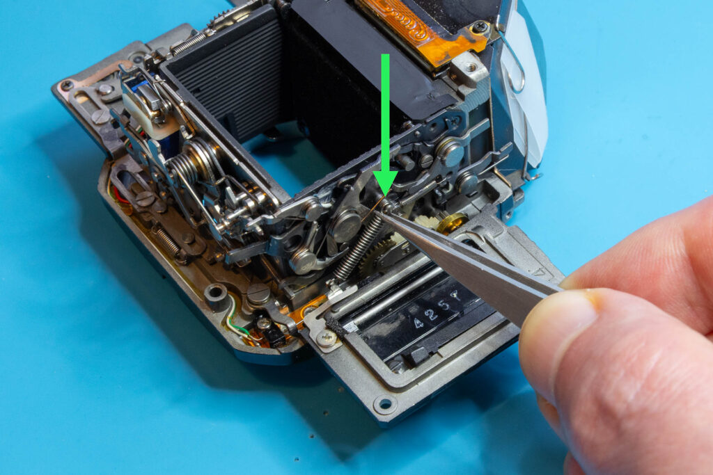
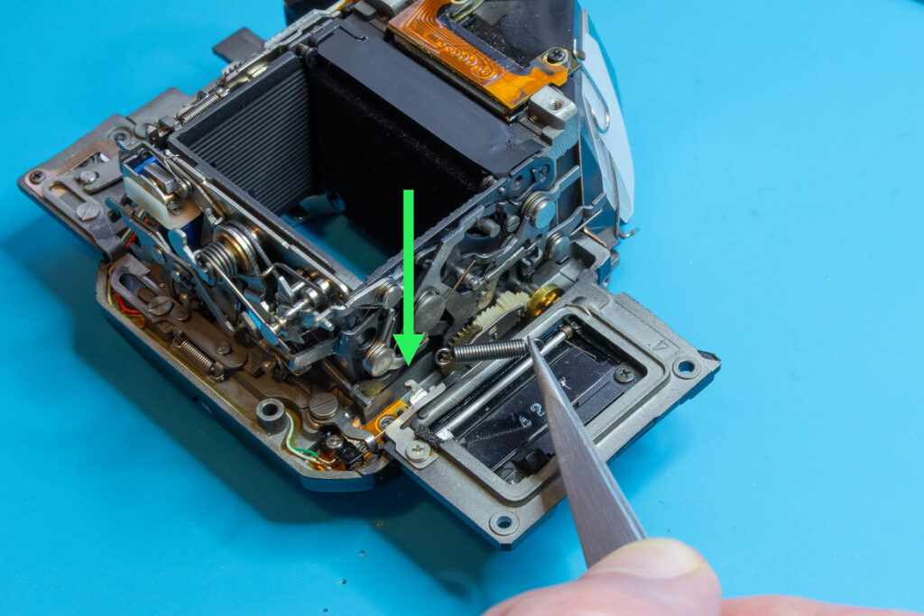
After this step, the following part is removed: mirror-lifting spring.
Step 3: Remove the Mirror-Control Unit and the Mirror
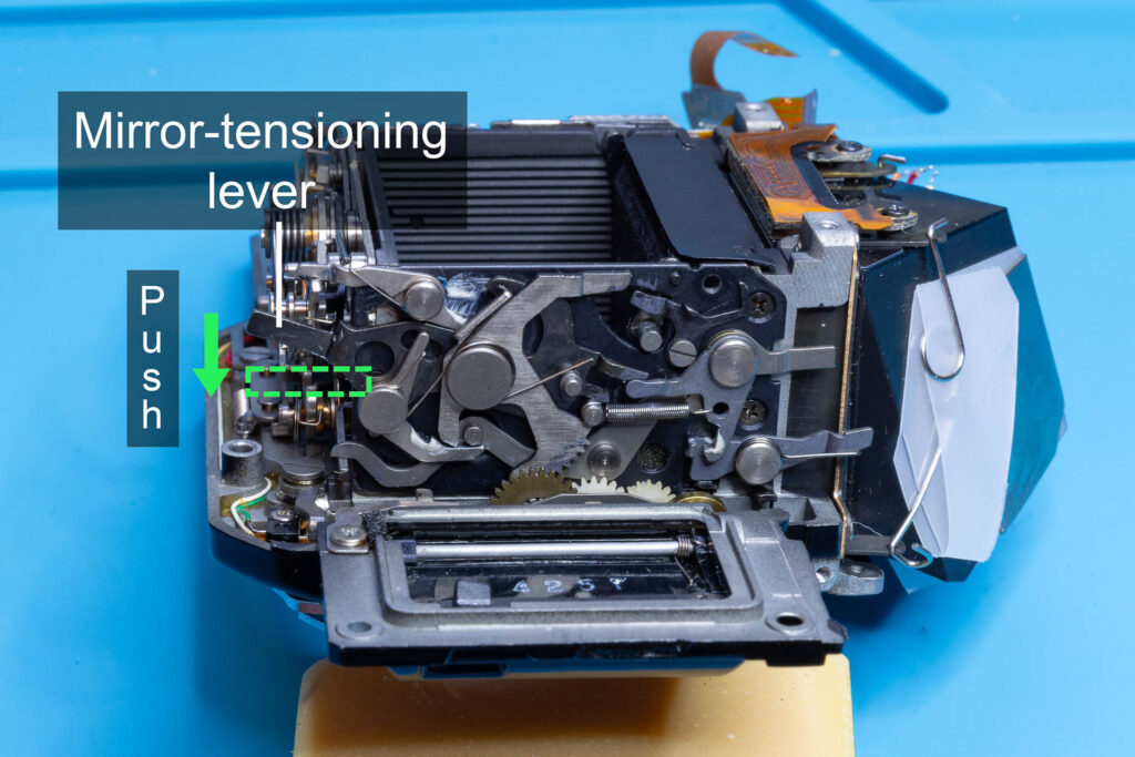
The mirror-control unit is connected to the frame of the mirror box by three screws, one on the left side, two on the right side. The two screws on the right side are always accessible. The screw on the left side is only accessible if you move the mirror-tensioning lever towards the front of the mirror box. The lever should lock into this position. The lever has a hole through which the screw can be accessed. Remove all three screws.
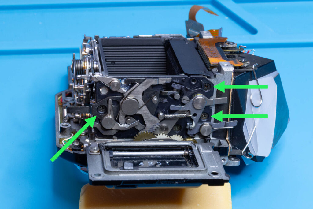
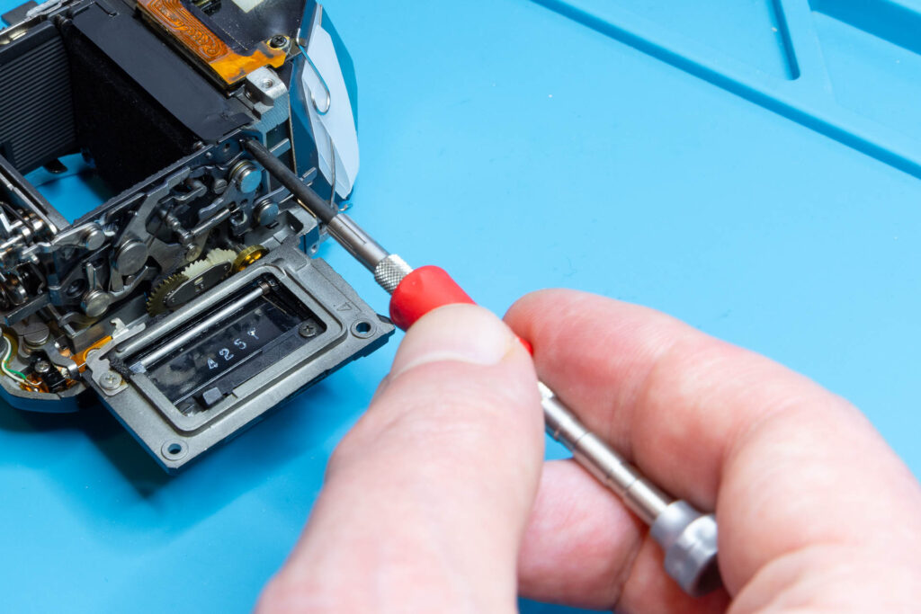
Grab the mirror-control unit with strong tweezers and tilt it until both the pivot and the post of the mirror disengage from it. Then, lift the mirror-control unit upwards to remove it. Next, carefully grab the mirror with tweezers (not on the glass, just on the pivot, post, or frame). Move it slightly to the right so that its other pivot disengages from the mirror box and then move it upwards to remove it.
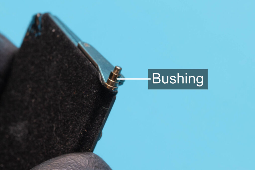
Attention: There is a tiny bushing sitting on the left pivot of the mirror that is used to limit the lateral movement (endplay) of the mirror. When you remove the mirror, this bushing will either still sit on the pivot, just fall off, or stick to the mirror box near the journal bearing of the pivot. In any case, don’t lose it!
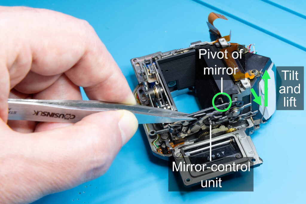
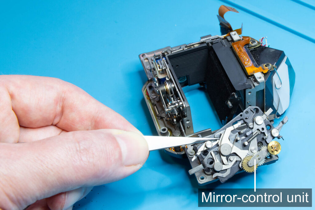
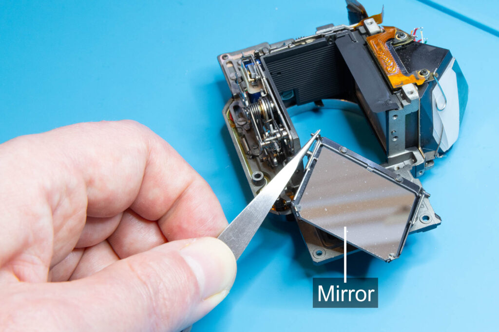
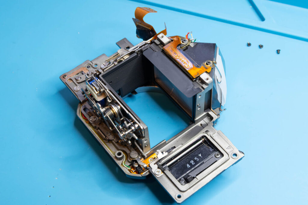
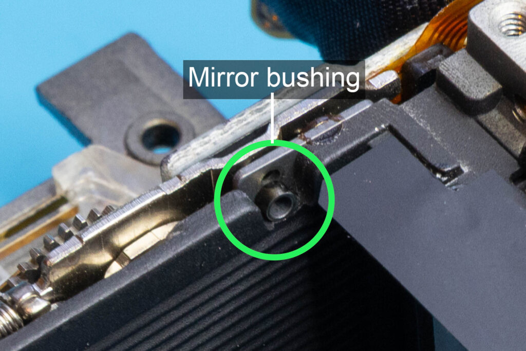
After this step, the following parts are removed (in removal order from left to right): three screws (1.65×1.3mm), mirror-control unit, mirror, bushing (length 1.15mm*).
(* To compensate for manufacturing tolerances, there are four different bushings available ranging from 1.00mm to 1.35mm.)
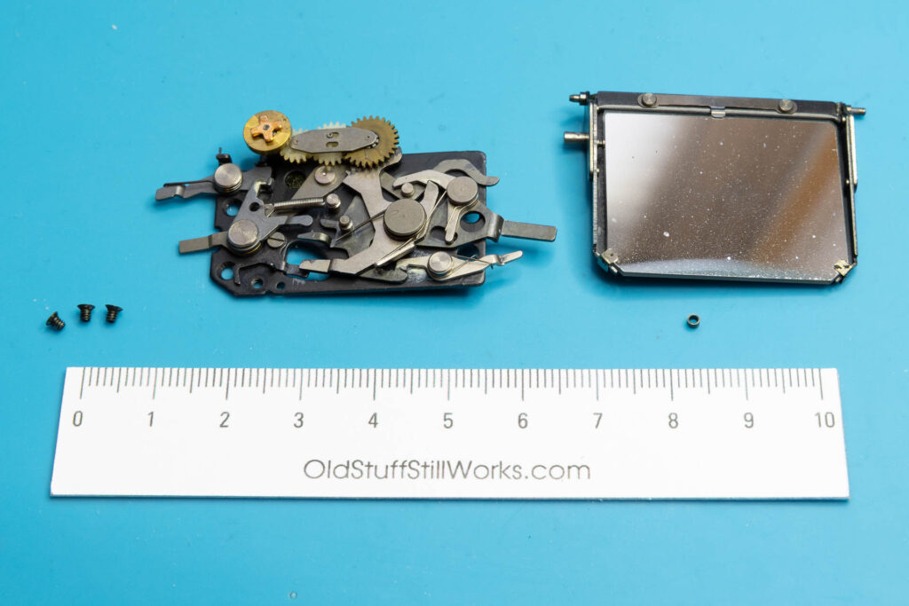
Step 4 (Optional): Clean/Repair the Mirror-Control Unit and/or the Mirror
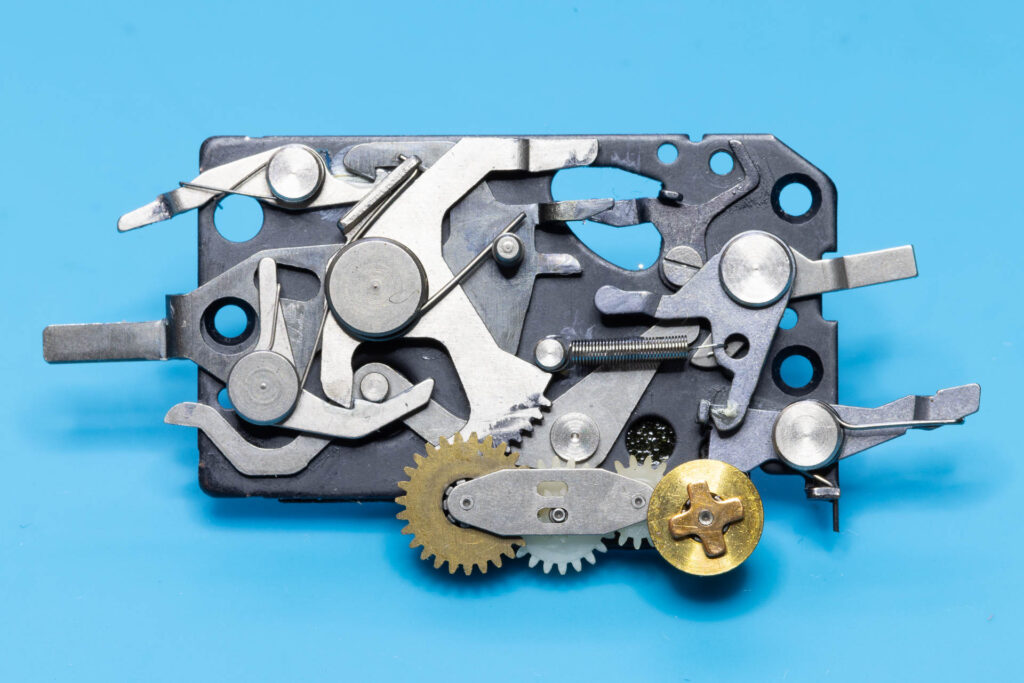
Both the mirror-control unit and the mirror were designed as assemblies to be replaced as a whole. Most of their components are riveted together and the assemblies cannot be disassembled without damage. Therefore, the usual case is that you swap the removed assemblies with other, either new or used ones. However, sometimes there might be a chance to salvage the original parts, for example if
- the gears and levers of the mirror-control unit no longer move smoothly due to dirt or dried oil/grease, or
- the mirror glass is dirty from the crumbles or sticky residues of a disintegrating mirror damper foam.
In these cases, it might be sufficient to solve the issues by a good clean and then reinstall the original parts.
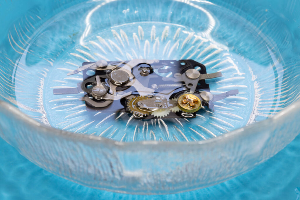
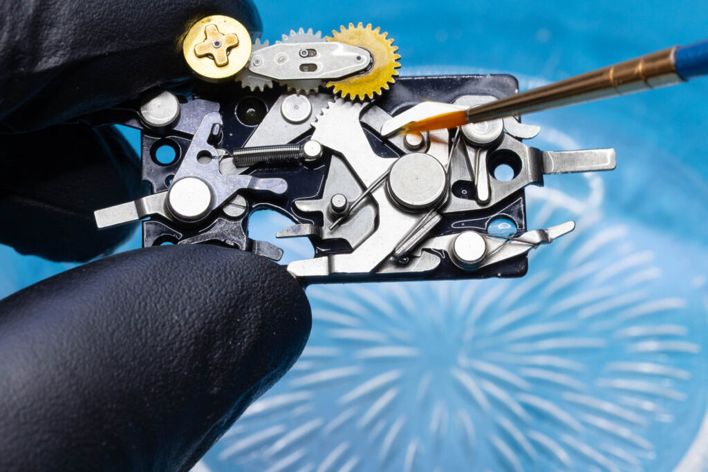
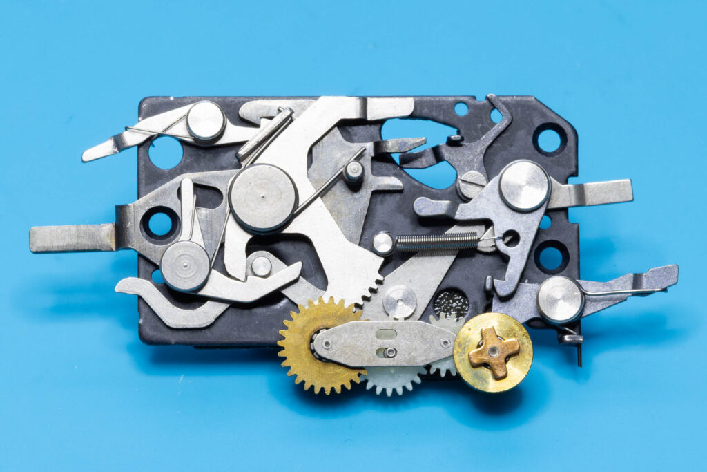
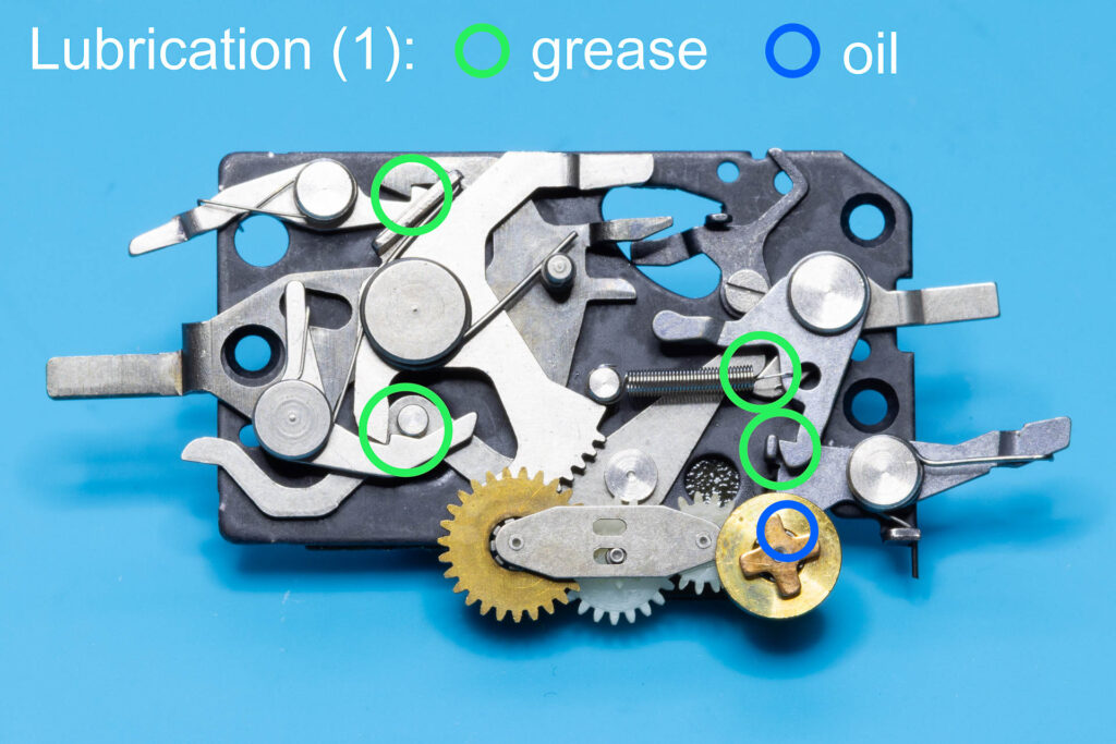
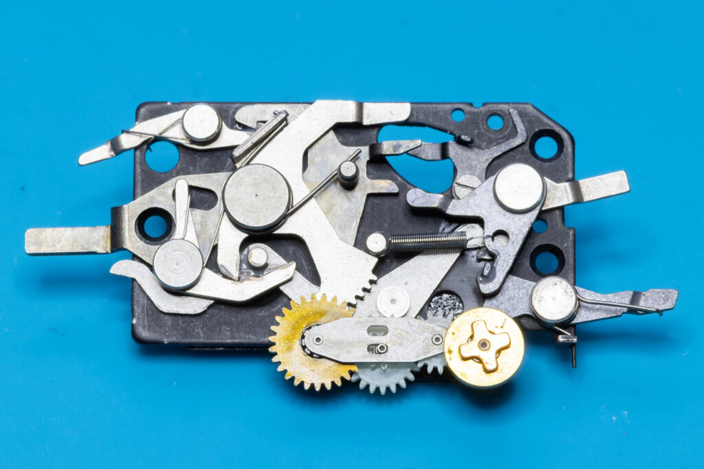
The mirror-control unit can be cleaned by soaking it in isopropyl alcohol (IPA) and using a small brush to remove the grime. Never use acetone instead since this will dissolve the rubber on the backside of the unit. After cleaning and drying, the mirror-control unit has to be relubricated. The picture below marks only the positions that should be lubricated while the mirror-control unit is not yet installed. Further lubrication is needed after installation of the unit (see Step 8 below).
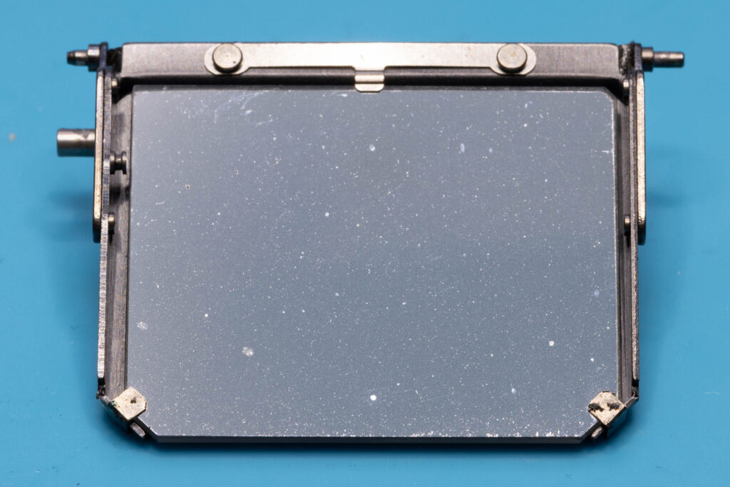
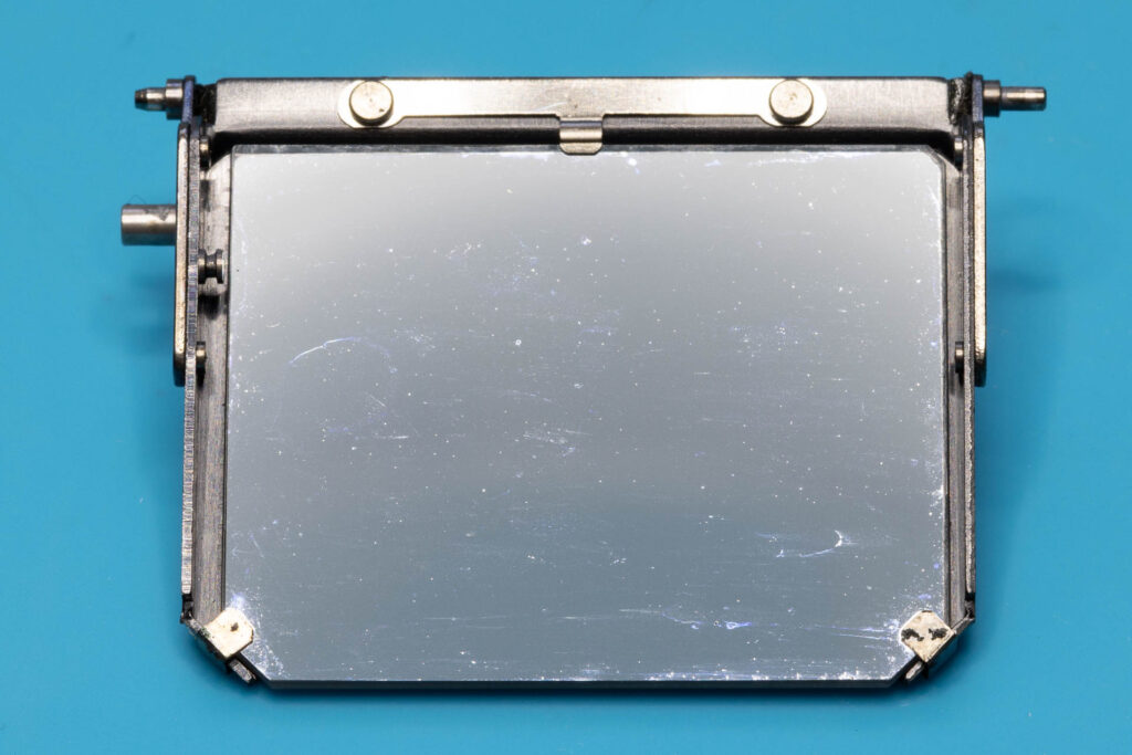
When cleaning the mirror you have to consider that its surface is very prone to scratches since it is front-silvered (the silver coating is on the upper side). Also, it can be difficult to clean the mirror without leaving streaks. Therefore, if in doubt it is better to not clean the mirror (except for blowing off dust). I use a cotton swab moistened with a special optics cleaner. The mirror on the pictures below was not very dirty and is only a bit cleaner after the procedure with some small streaks remaining.
Step 5: Install the Mirror and the Mirror-Control Unit
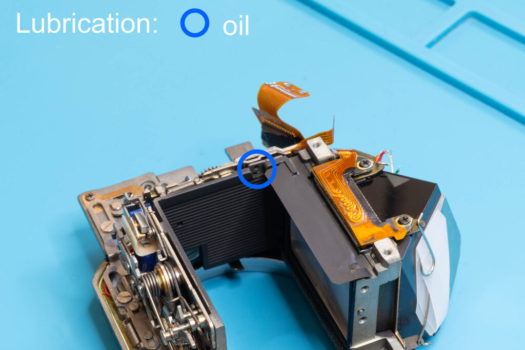
First, put a tiny(!) amount of oil into the journal bearing of the mirror pivot on the left side of the mirror box. “Tiny” means to only slightly wet the bearing with oil (a “drop” would be way too much). For example, by using the tip of a toothpick lightly moistened with oil.
Put the bushing on the left pivot of the mirror (seen from behind). Then, put the pivot into the bearing on the left side of the mirror box. Position the mirror so that it is about parallel to the focus screen and stands on its own.
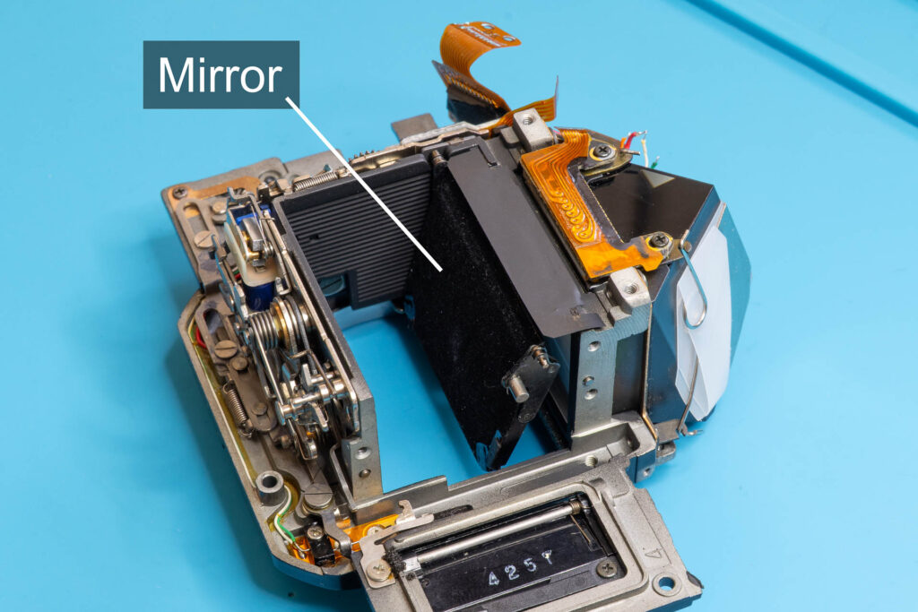
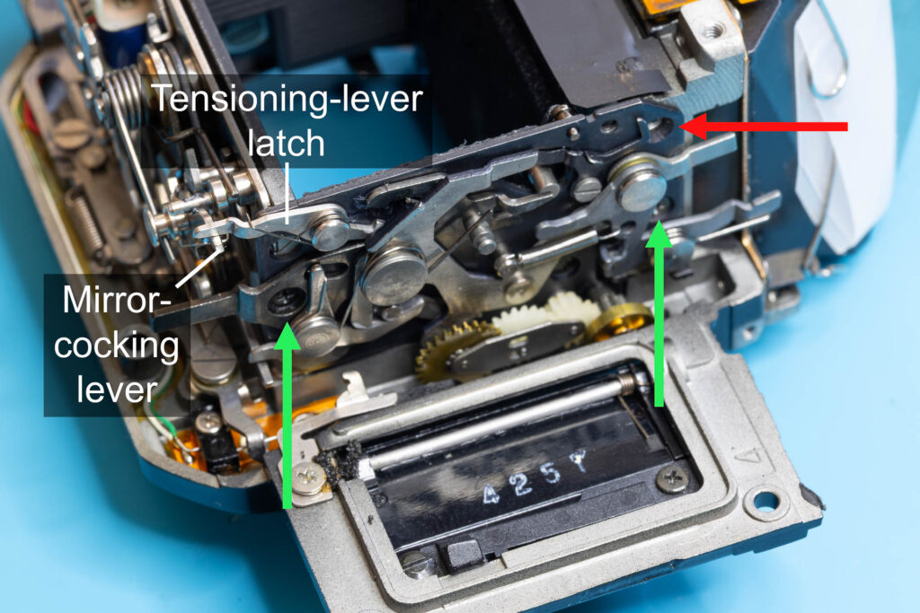
Place the mirror-control unit on the right side of the mirror box, its upper side slightly tilted to the right. Then, bring the unit to a vertical position so that the right pivot of the mirror slides into the bearing on the unit. Make sure that the tensioning-lever latch is sitting over the mirror-cocking lever of the auto-diaphragm unit. Secure the unit with the screw on the left side and the lower screw on the right side. Don’t screw in the upper right screw yet!
Step 6: Install the Mirror-Lifting Spring
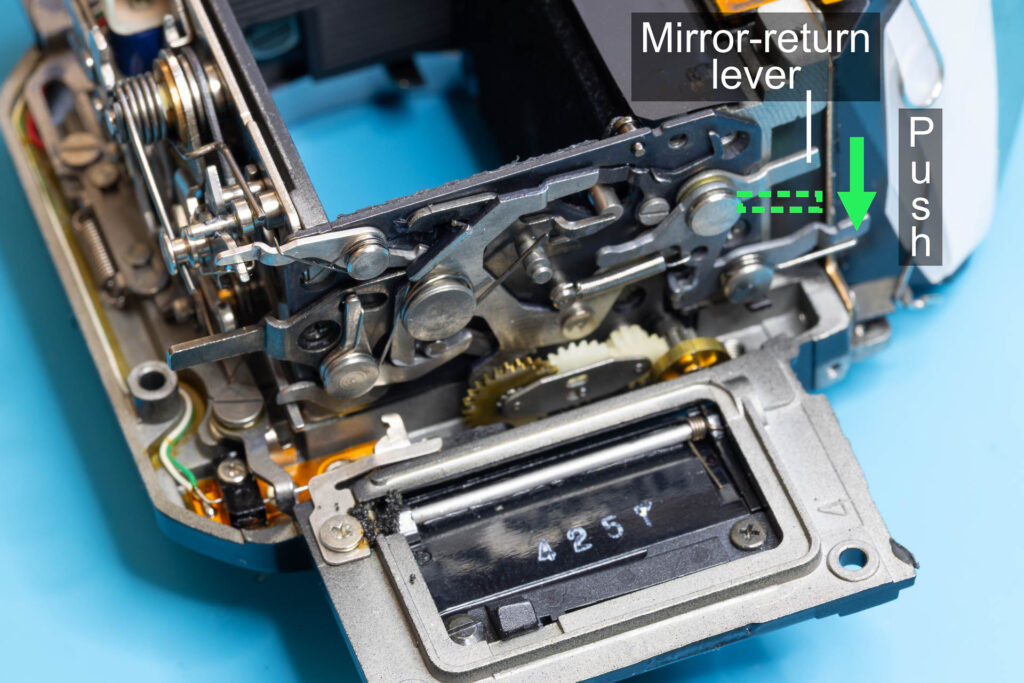
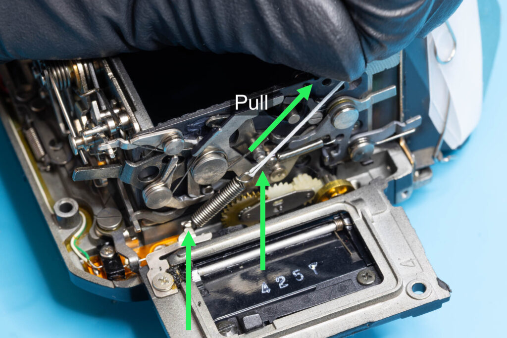
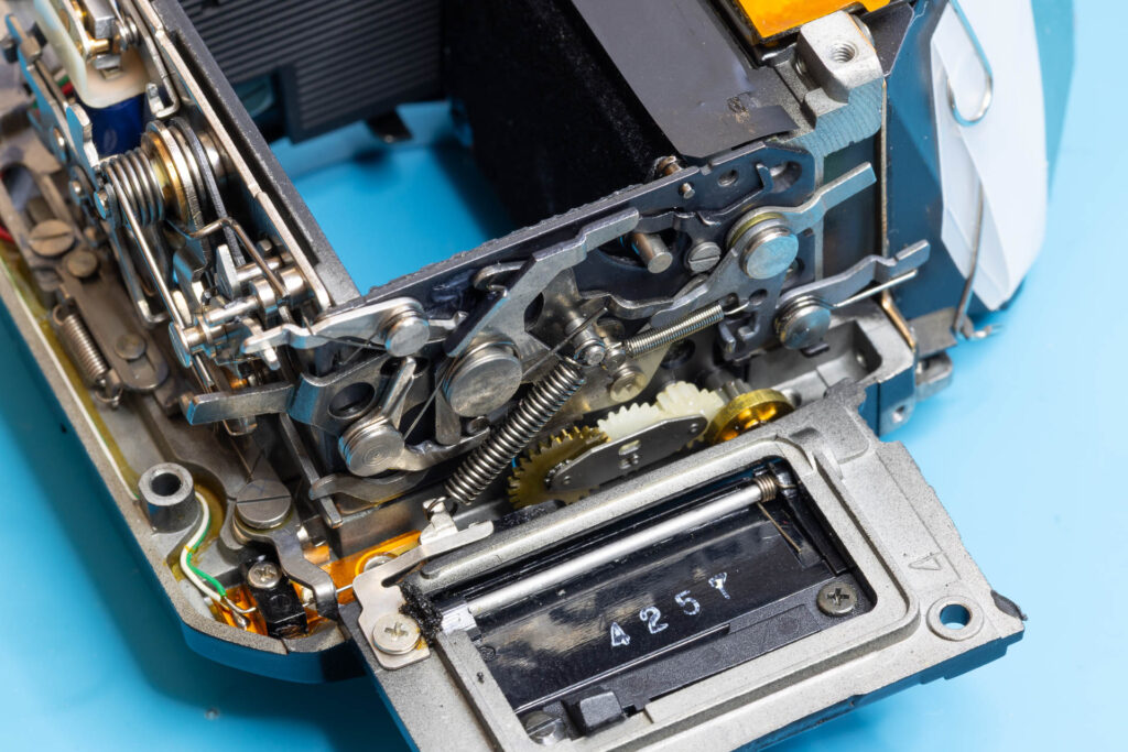
Since the mirror-lifting spring is a quite strong extension spring, installation can be a bit tricky. I recommend doing it the following way: First, push the mirror-return lever of the mirror-control unit towards the front of the mirror box to flip down the mirror. This will reduce the distance between the two mounting points of the spring. Then, put a piece of string (like a strong sewing yarn) through one loop of the spring and attach the other loop of the spring to the hook on the frame of the mirror box. Use the string to extend the spring until its loop attaches to the post on the mirror-tensioning lever. Finally, remove the string.
Step 7: Install the Mirror-Return Spring
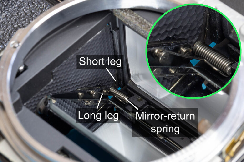
First, put the mirror-return spring into the upper left corner of the mirror box (seen from the front). Place the spring so that its short leg is on the left side and its long leg on the right side. The short leg has to point to the back of the mirror box, the long leg to the front of the mirror box. Then, screw in the screw pin on which the spring sits into the mirror-control unit. This will secure the position of the spring.
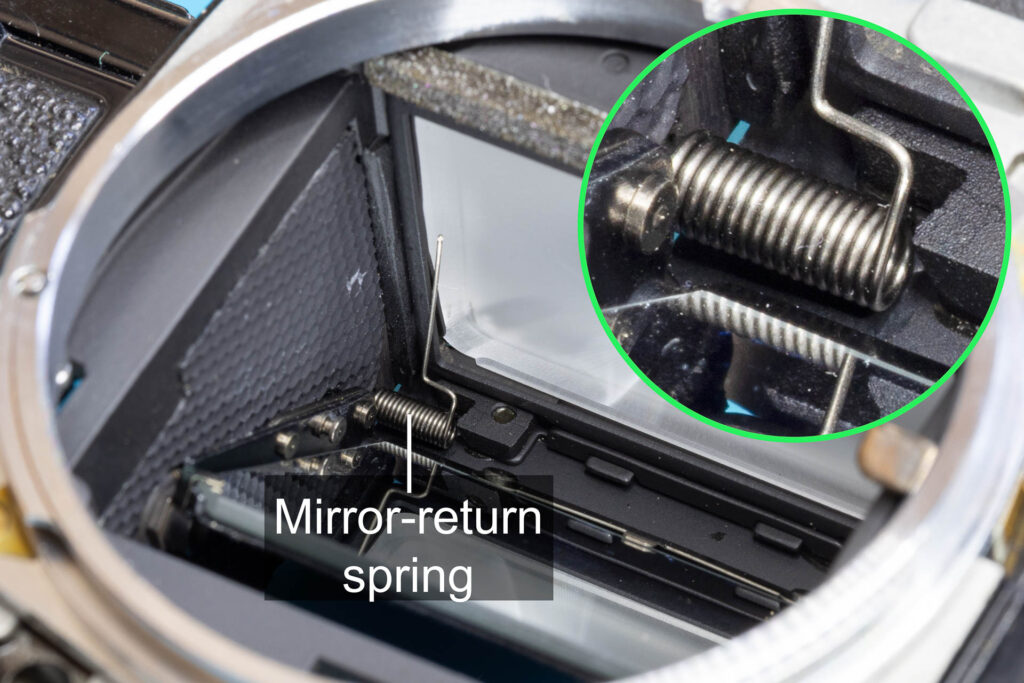
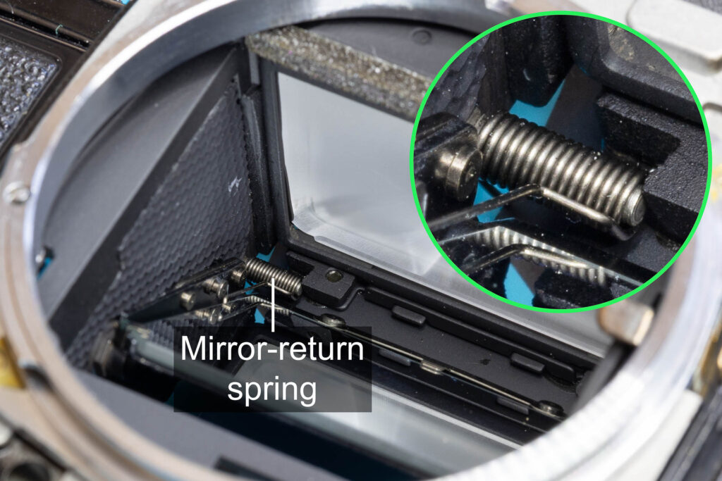
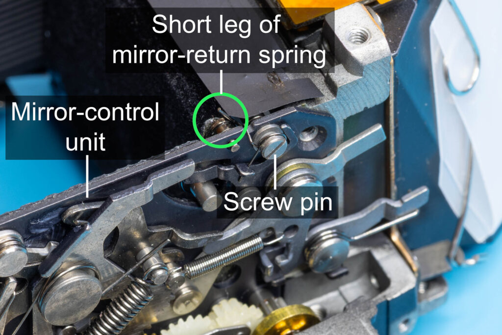
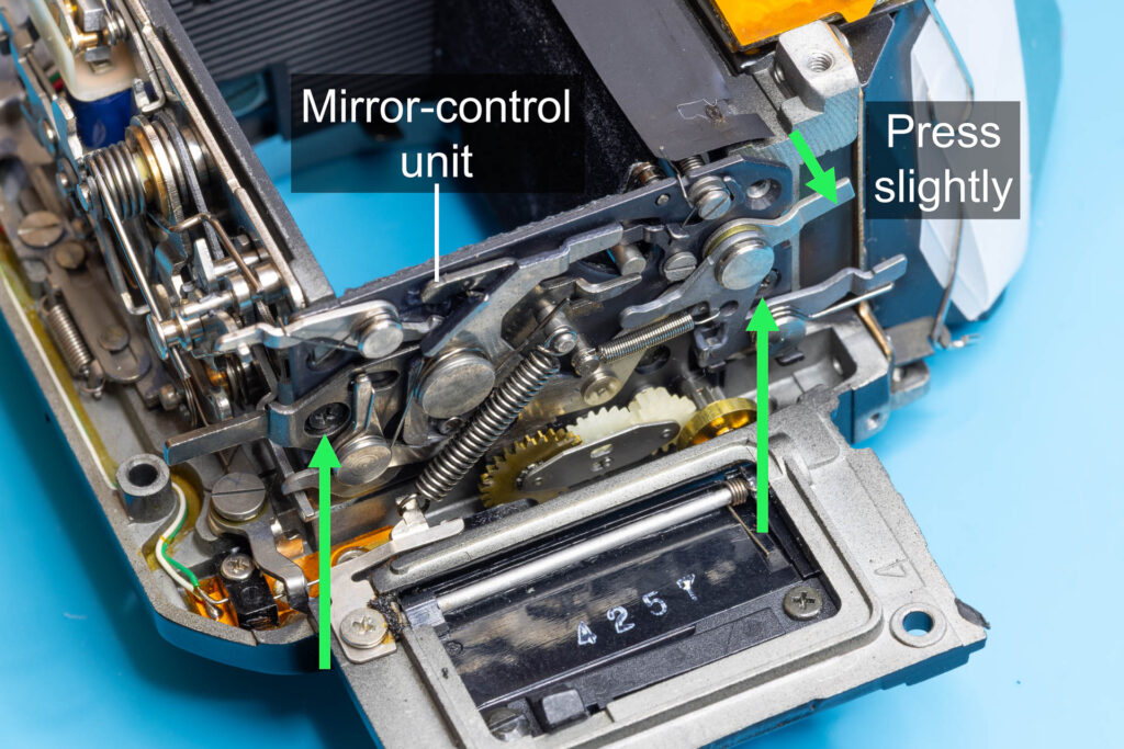
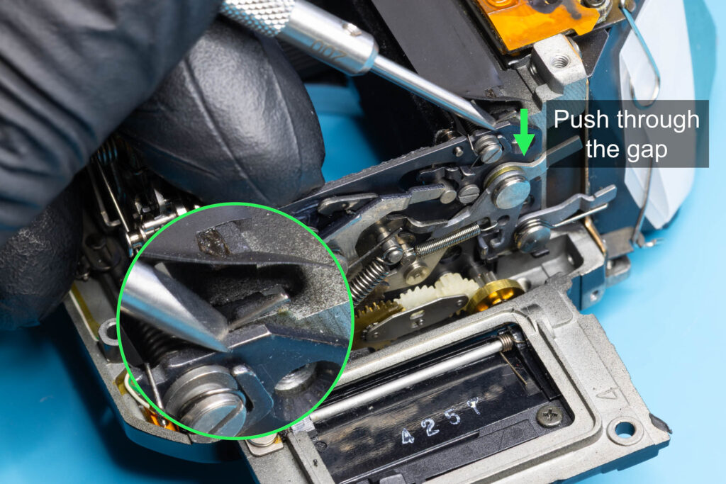
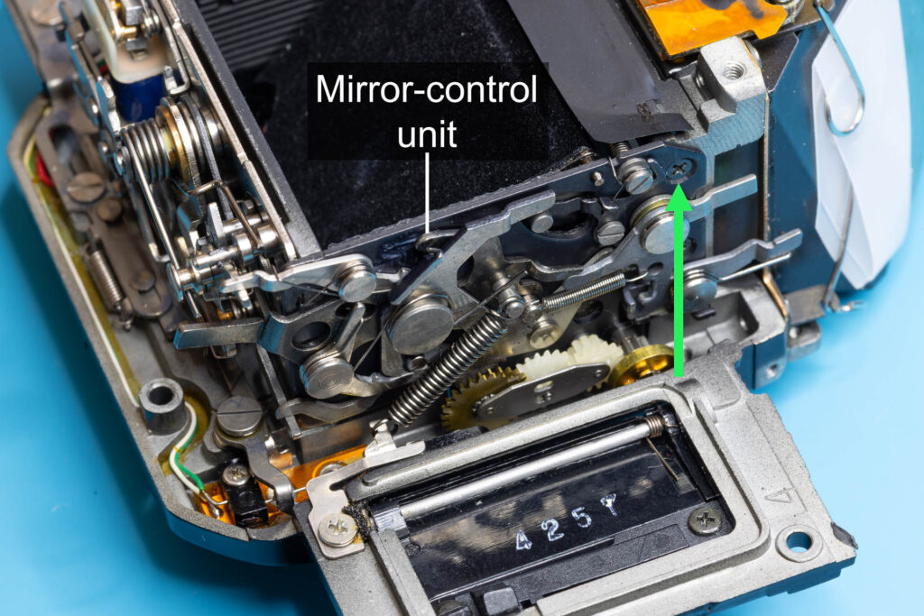
When you turn the mirror box onto its front, you should see the short leg of the mirror-return spring sticking out from under the light trap. Loosen the left screw and the lower right screw slightly (half a turn should be sufficient) to give the mirror-control unit some slack. Press the unit slightly to the right. This should open a gap of about 1mm between the frame of the mirror box and the mirror-control unit. Use a small flat-head screwdriver (blade width ~2mm) to push the leg of the spring through this gap. The angle between the upper edge of the mirror-control unit and the leg should be a bit more than 90°. Then, push the mirror-control unit back against the frame of the mirror box to close the gap. While holding the mirror-control unit in this position with one hand, use the other hand to fasten the left screw and the lower right screw again. Afterwards, screw in the upper right screw. Finally, turn the mirror box onto its back again. Place the short leg of the mirror-return spring into the upper left corner that is formed by the mirror-control unit and the frame of the mirror box. Place the hook of the long leg over the pin on the side of the mirror unit.
Step 8 (Optional): Some More Lubrication
I already described part of the lubrication process of the mirror-control unit in Step 4 above. That part can be performed both when the mirror-control unit is removed and when it is installed. The second part of the lubrication process described here should be done when the mirror-control unit is installed. See the picture below.

Step 9: Reinstall the Mirror Box and the Top Cover
Follow the procedure described in this blog post to install the mirror box. Then, follow the procedure described in this blog post in reverse order to install the top cover.
That’s all.