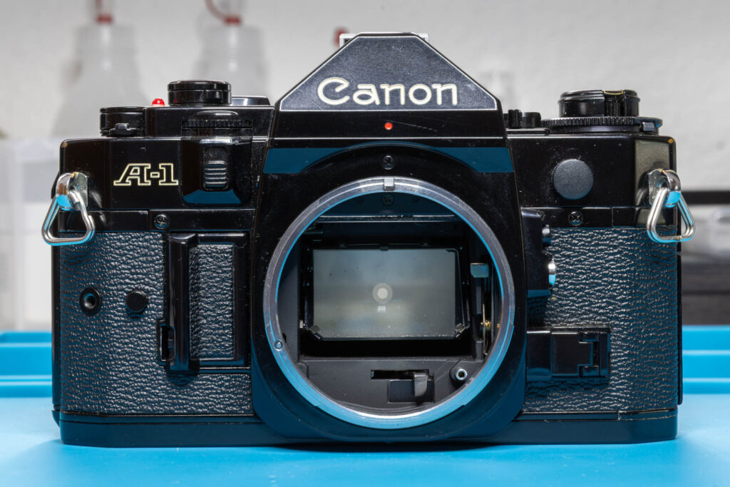
Disclaimer: The repair procedure I present in this post is inspired by the official service manual and renowned repair articles but mainly reflects my own experience. The description may be incomplete and might even contain errors. Consider that I am just a self-taught hobbyist, not a trained professional. Copy this procedure at your own risk! Also, consider that any attempt to disassemble and repair a camera carries a certain risk to worsen its condition or to even breaking it completely.
When a Canon A-1 has to be repaired, the process often requires the removal of the mirror box (also called ‘mirror cage’ or ‘mirror assembly’). After the actual repair is finished, the mirror box has to be reinstalled. In this post, I present the installation steps that are necessary in the order that works best for me.
General Principle
I assume that you removed the mirror box according to the description in my Canon A-1: How to Remove the Mirror Box blog post. In principle, the installation of the mirror box is carried out in the reverse order of the steps described there. Therefore, I will keep the description in this post rather short.
Tools
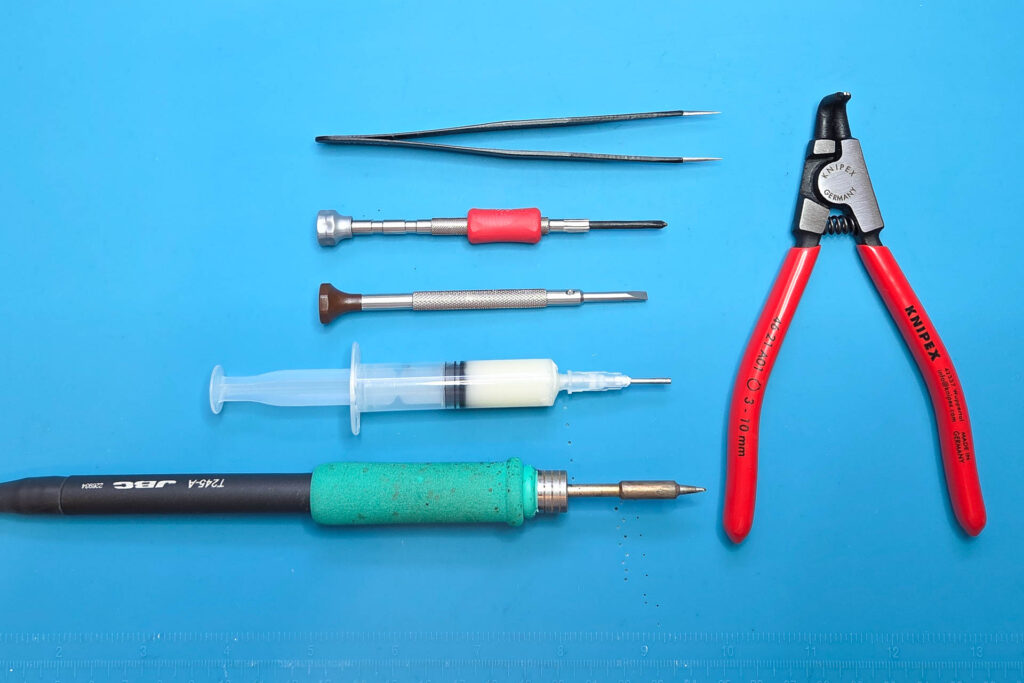
To install the mirror box of a Canon A-1, you need a certain set of tools and materials. These are my recommendations:
- JST screwdriver #00
(A Phillips screwdriver PH00 or PH0 might work “somehow” but be aware that it might damage the screw head.) - flat-head screwdriver ≥ 3mm (blade thickness ≤ 0.5mm!)
- tweezers with sharp points
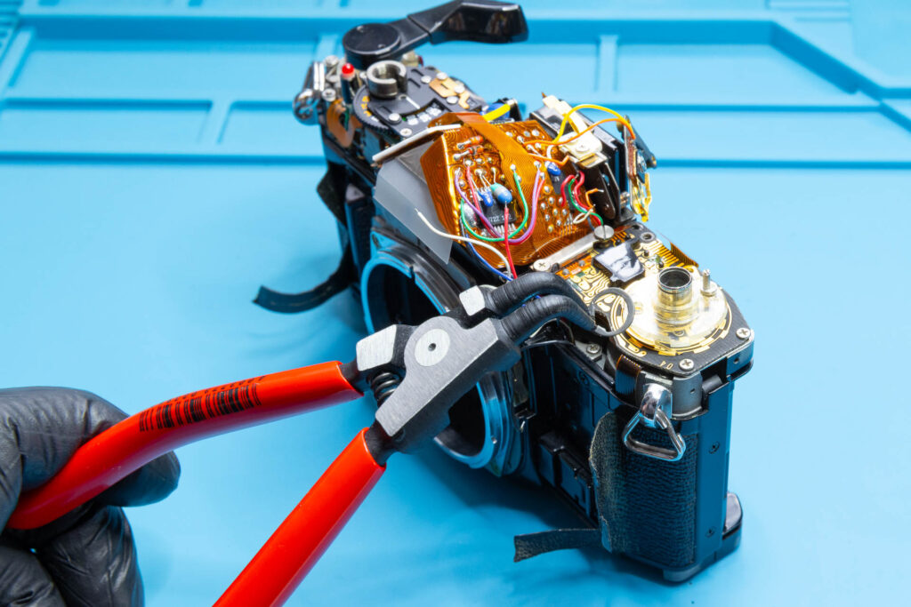
- circlip / snap ring pliers for small rings, like a Knipex 46-21-A01
- adjustable soldering iron with small tip
(I use a JBC BT-2BWA soldering station with a C245-906 cartridge with small tip [chisel 1.2×0.7mm]. For leaded solder, I operate it at 300 °C.) - [optional] acid-free soldering flux (might reduce the soldering time)
- isopropyl alcohol (IPA)
- glue suitable for leatherette, like Pliobond 25 or other contact cement
(I use a water-based Tolex rubber cement.)
Step 1: Install the Film Advance Lever (Temporarily)
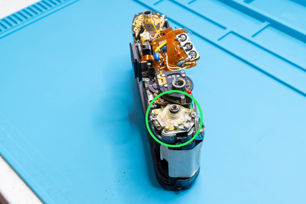
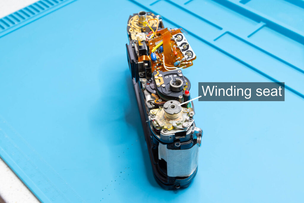
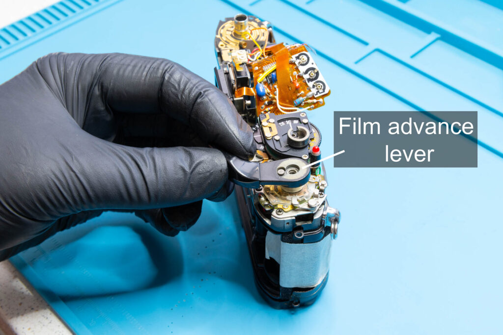
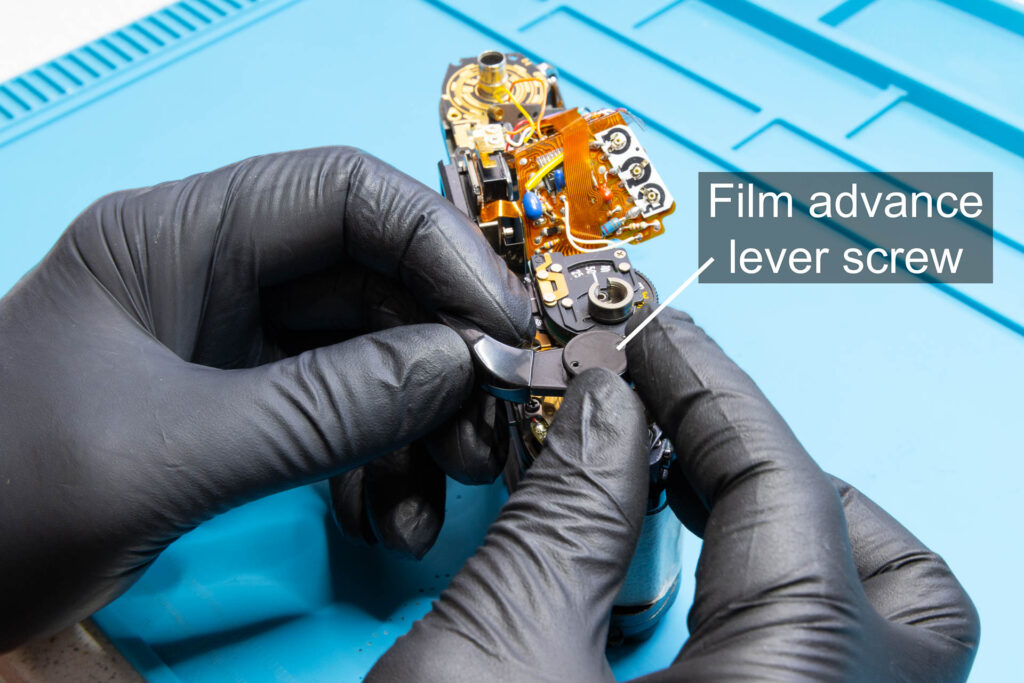
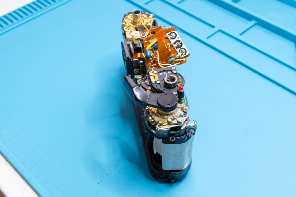
To check the correct functioning of the shutter after installation of the mirror box, you will have to cock and release the shutter a couple of times. To prepare for this, install the film advance lever temporarily. You only need to install the winding seat, the film advance lever, and the film advance lever screw. No need to install all the washers, the main switch lever, and the multiple exposure lever.
Step 2: Insert the Mirror Box
This step corresponds to Step 8 of the Canon A-1: How to Remove the Mirror Box instructions.
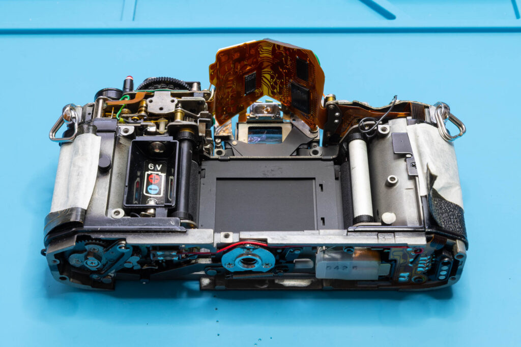
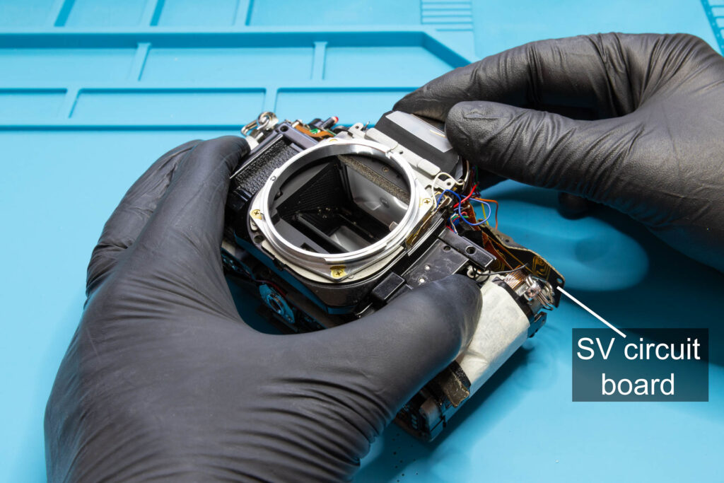
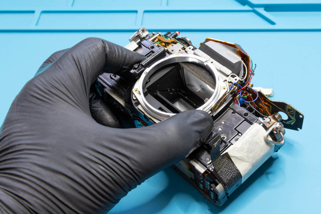
The insertion of the mirror box into the camera chassis is easier when the shutter is released. If it is still cocked, you can release it mechanically as described in Step 3 of the Canon A-1: How to Quick Test the Shutter Without a Battery instructions. Place the camera chassis on its back, take the mirror box, and insert it into the chassis. A bit of tilting and wiggling will be necessary. It might help to open the battery door and put a finger into the battery chamber for extra grip. Make sure that the two flexible boards and wires 8, 10, 11, 12, and 13 of the mirror box slip underneath the SV circuit board without them getting stuck or bent. When successful, the mirror box has to lay flat in the camera chassis without gaps.
Step 3: Fasten the Mirror Box and Perform Initial Tests
This step corresponds to Step 7 of the Canon A-1: How to Remove the Mirror Box instructions.
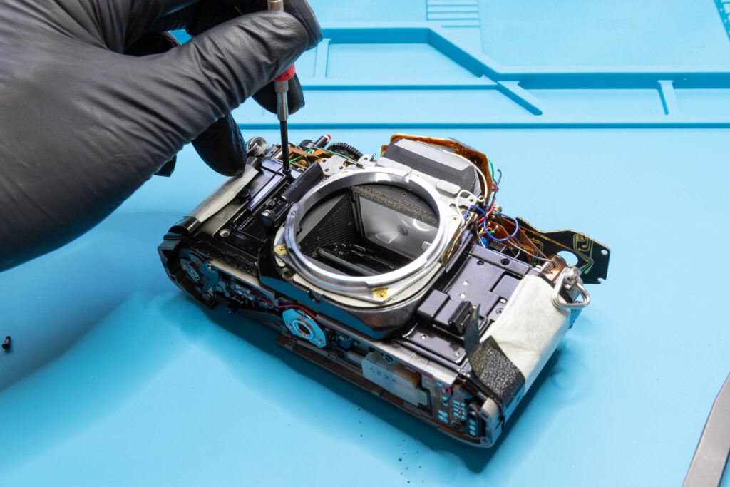
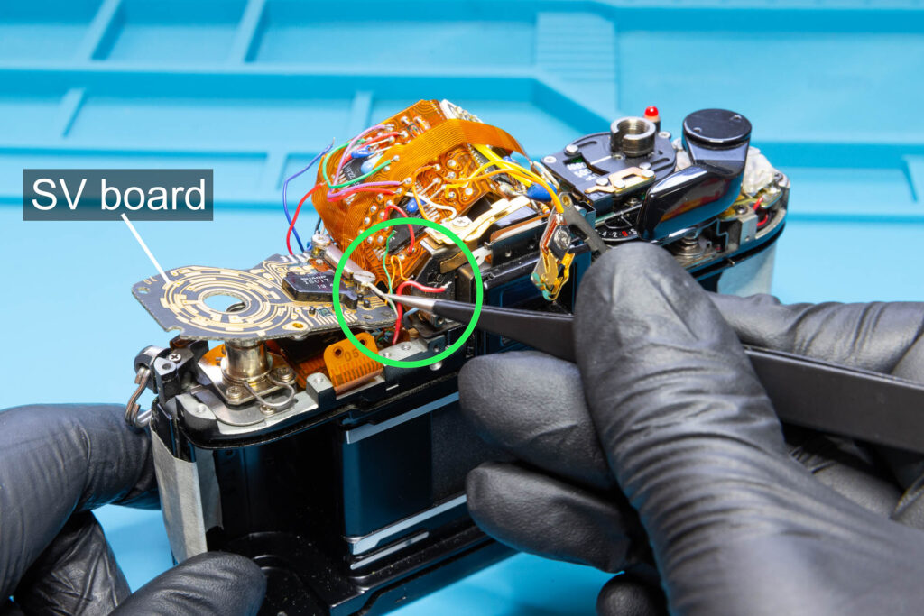
Fasten the mirror box using five screws. Then, check that the wires 8, 10, 11, 12, and 13 sticking out from under the SV circuit board. If not, use tweezers to pull them out carefully from under the SV board. Position the wires so that they sit between the AT flex board (left) and the SAVE connector (right). Finally, push down the SV circuit board.
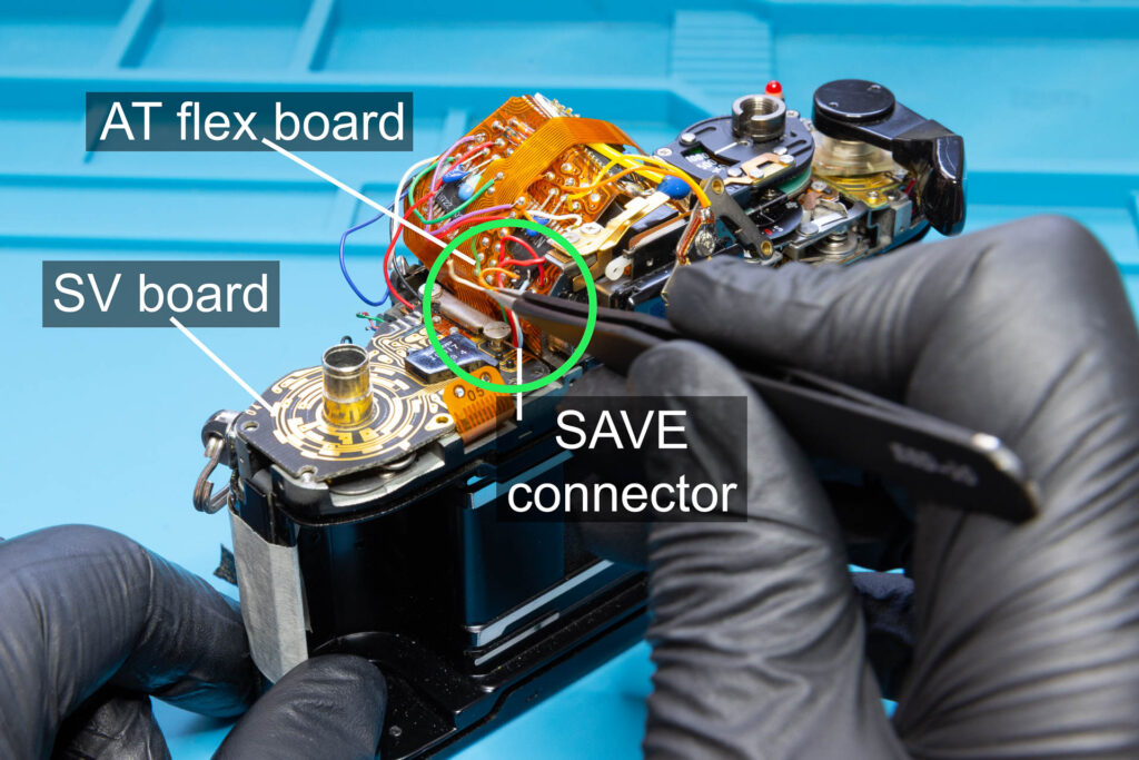
Perform initial tests by cocking the shutter and releasing it mechanically. Check that the mirror moves up and down when the shutter is released. Repeat a couple of times.
Step 4: Screw in the Eyepiece Screws
This step corresponds to Step 5 of the Canon A-1: How to Remove the Mirror Box instructions.
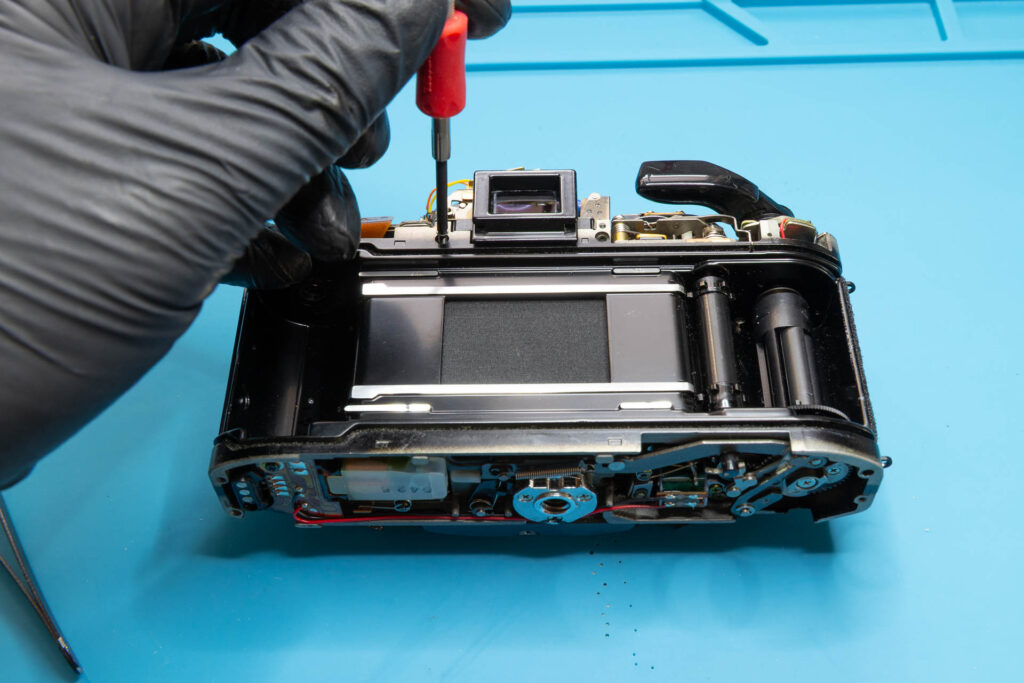
Screw in the two eyepiece screws left and right of the eyepiece.
Step 5: Fasten the SV Circuit Board
This step corresponds to Step 4 of the Canon A-1: How to Remove the Mirror Box instructions.
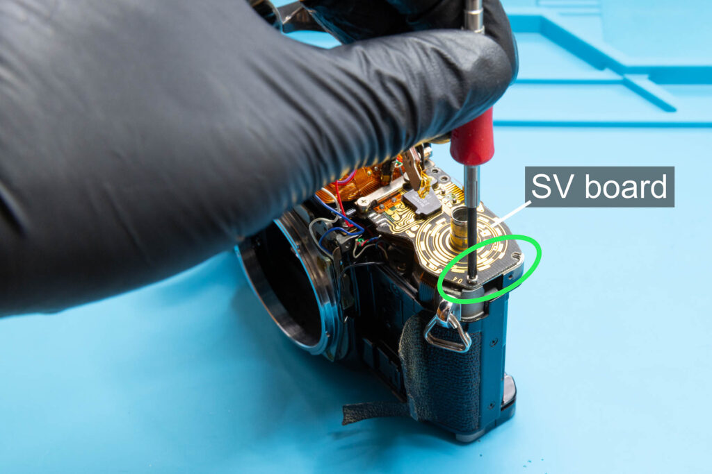
Put the metal bar under the SV circuit board (rounded side inwards) and secure it with two screws.
Step 6: Install the ASA Brush Plate
This step corresponds to Step 3 of the Canon A-1: How to Remove the Mirror Box instructions.
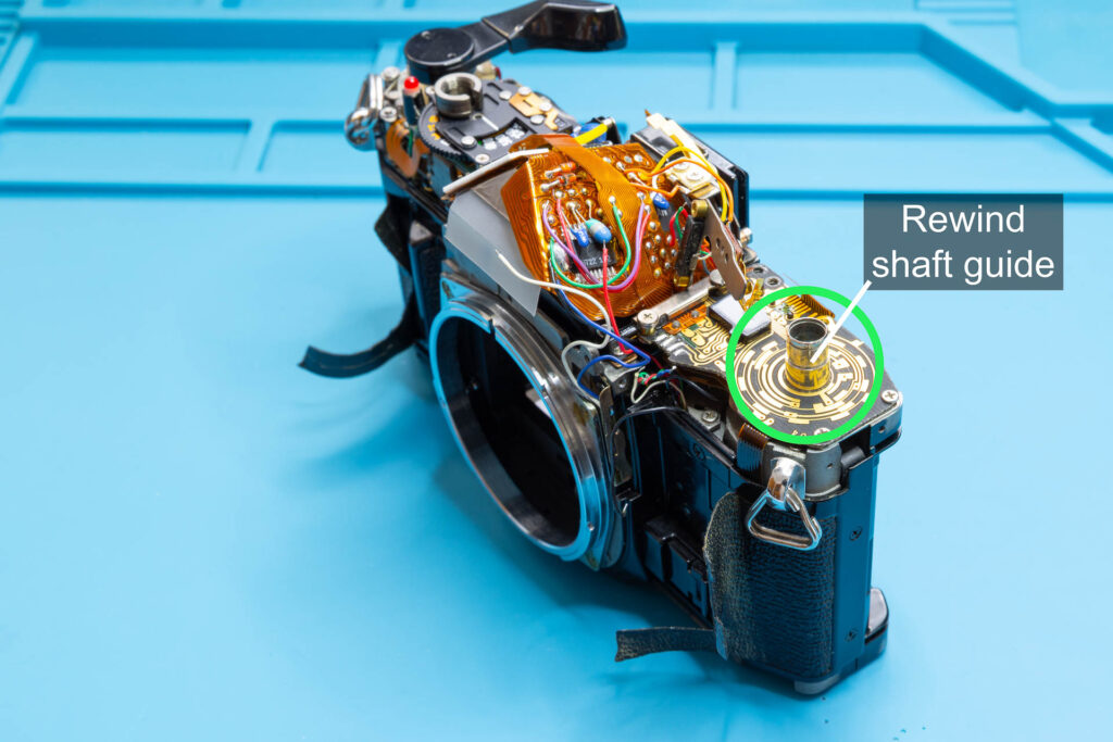
Put the ASA brush plate (with contact wipers downwards) on the rewind shaft guide and secure it with the snap ring.
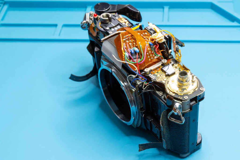
Step 7: Close the Flexible Board Connectors
This step corresponds to Step 2 of the Canon A-1: How to Remove the Mirror Box instructions.
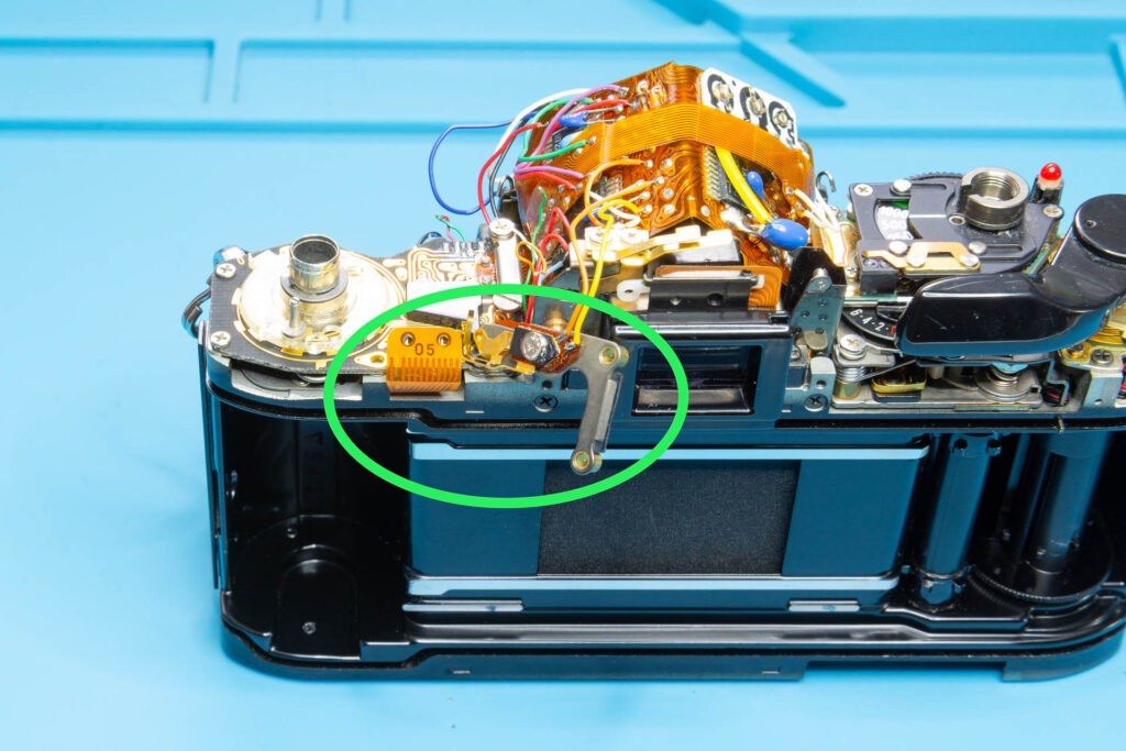
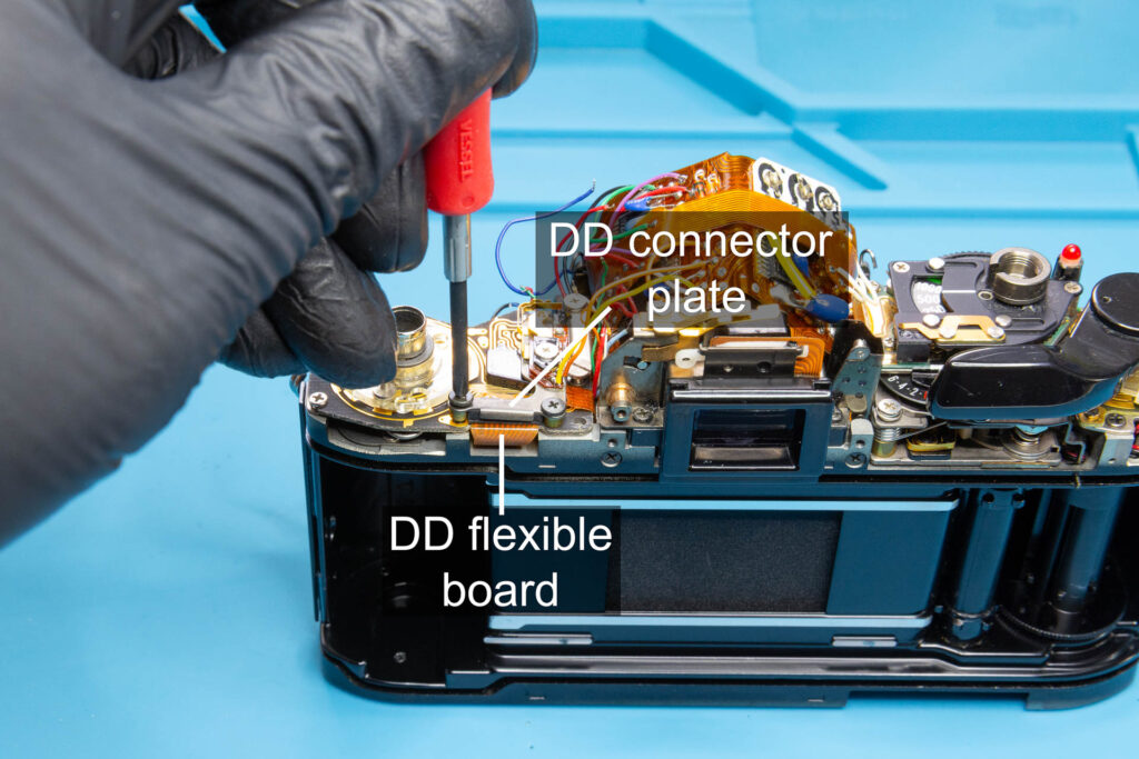
Install the DD connector plate (two screws). Then, install the SAVE connector plate (one screw). Tighten the slotted screw of the SAVE connector plate. Before you install the plates, make sure that the respective flexible boards are in the correct position with their holes on the corresponding position pins.
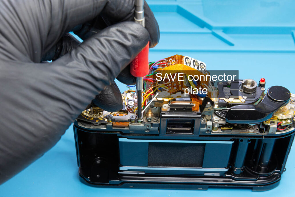
Step 8: Resolder the Wires and Perform Final Tests
This step corresponds to Step 1 of the Canon A-1: How to Remove the Mirror Box instructions.
Resolder the wires you desoldered when you removed the mirror box:
- Resolder wires 9 to 13 to the AT flexible board.
- Resolder wires 5 to 8 to the main flexible board.
- Resolder wires 1 to 4 to the SV circuit board.
Before you resolder a wire to the corresponding soldering point, apply a tiny amount of soldering flux. This will improve the quality of the solder joint and reduce the soldering time.
If you removed the black rubber band that holds the main flexible board down when you removed the mirror box, also install this rubber band.
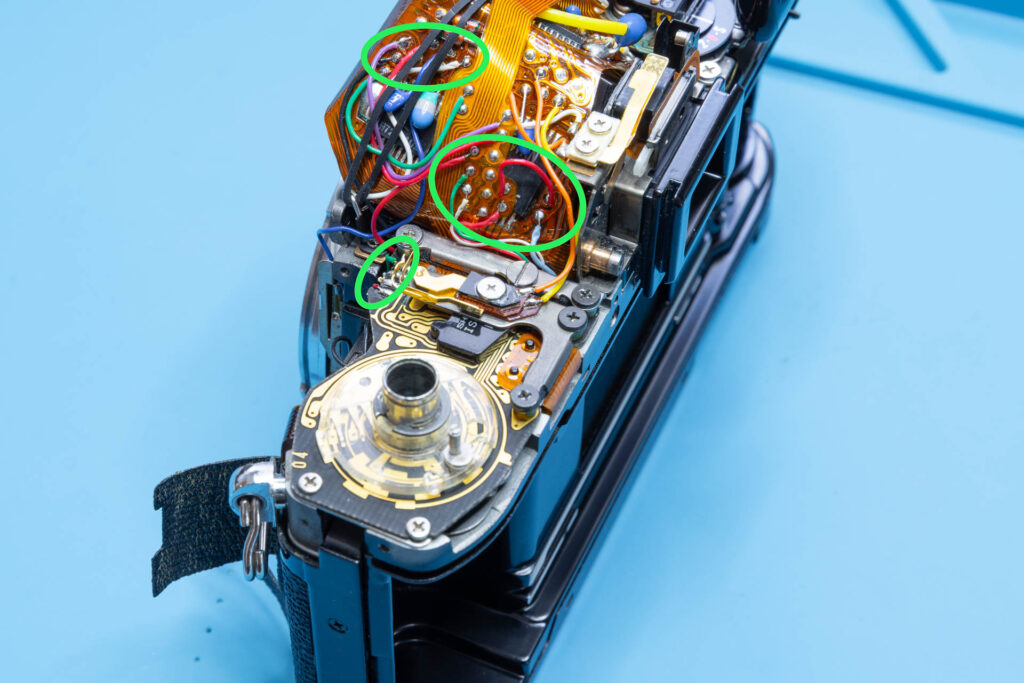
When identifying the wires and the corresponding soldering points, don’t just rely on the pictures in the Canon A-1: How to Remove the Mirror Box instructions. Check also the pictures you took during disassembly. During the production run of the Canon A-1, the colors of the wires and the position of the soldering points might have changed.
After all wires have been resoldered, insert a battery and check the functioning of the shutter and the mirror. You can also attach a lens and check if the auto diaphragm mechanism works correctly.
Step 9: Reglue the Front-Facing Leatherette
This step corresponds to Step 6 of the Canon A-1: How to Remove the Mirror Box instructions.
Reglue the leatherette only after you have checked that the installation of the mirror box was successful. Otherwise, you might have to remove the leatherette again to fix a problem.
There are different opinions on the Internet on which glue is best to use for camera leatherette. Often, the use of a contact cement like Pliobond 25 is suggested. I will not take part in these discussions. I just want to emphasize two points you should consider:
- It has to be possible to remove the leatherette again without damaging it for future repairs.
- The leatherette (faux leather) is made of plastic, probably polyurethane or polyvinyl chloride. The glue must not dissolve this material.
Personally, I use a water-based Tolex rubber cement. Just because I have it anyway, it doesn’t smell, and the results are satisfactory.
Before you reglue the leatherette, use isopropyl alcohol (IPA) to clean the camera chassis and the underside of the leatherette from old glue and grime.
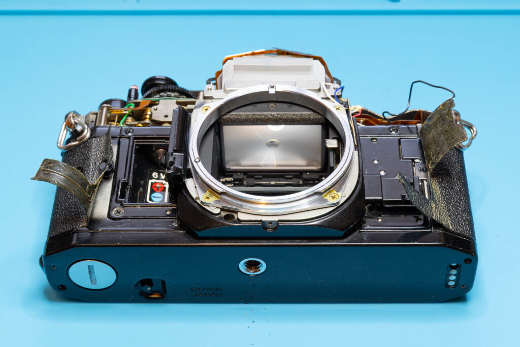
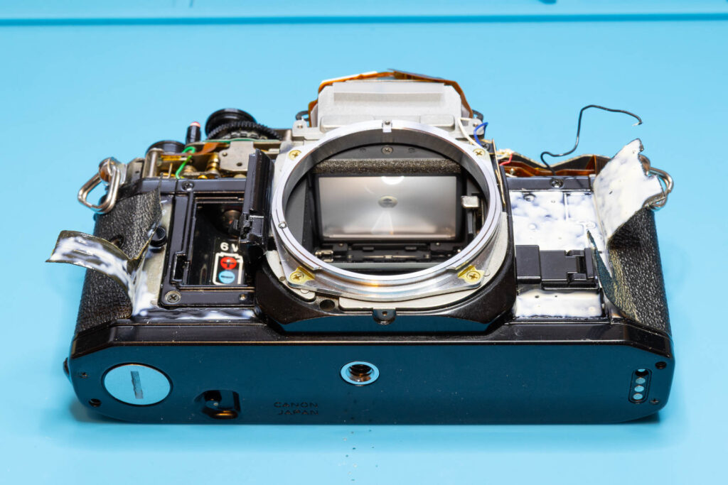
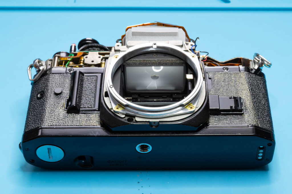
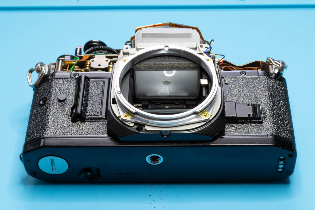
With this step, the installation of the mirror box is complete.
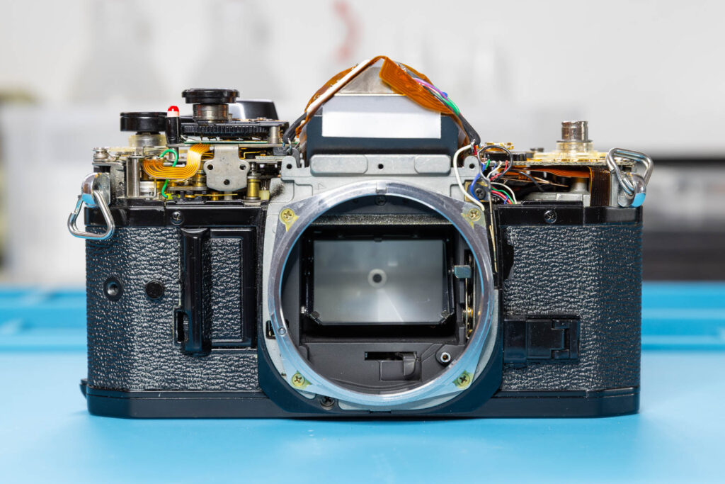
That’s all.