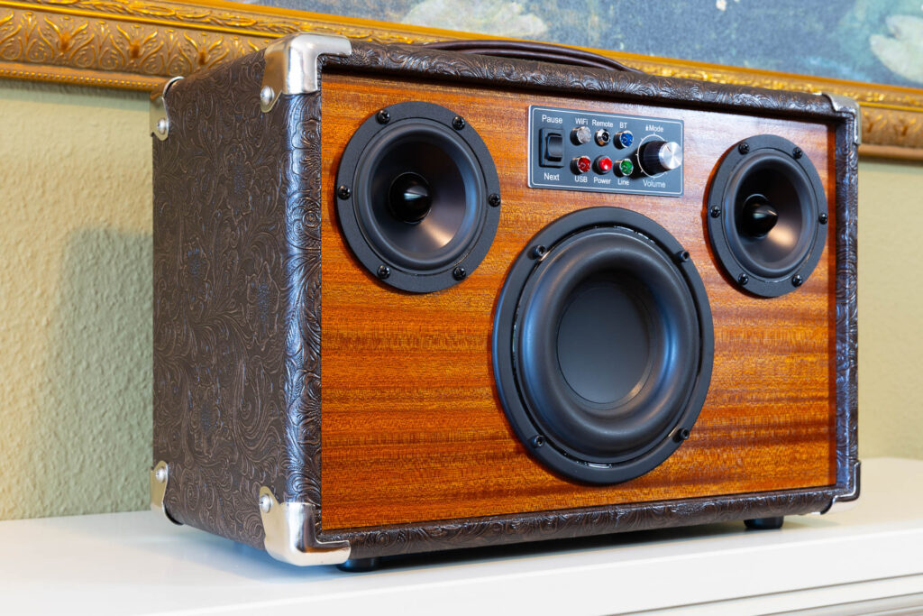
Disclaimer: In this post, I present a project that I finished successfully. However, it is not meant as a detailed construction manual. The description may be incomplete and might even contain errors. Feel free to use it as an inspiration for your own project but scrutinize the information presented here and use your common sense. Build at your own risk!
The boombox needs a couple of control elements, indicators, and input ports that have to be accessible from the outside. I decided to put them on three dedicated panels:
- a control panel on the front of the cabinet
- an input panel on the back of the cabinet
- a power supply panel on the back of the cabinet
In general, all these panels are built in the same way:
- A rectangular cutout (with rounded edges) is made in the 12mm plywood of the front or back piece, respectively.
- Around this cutout, a recess is milled that is 2mm deep and 5mm wider than the cutout (in each direction).
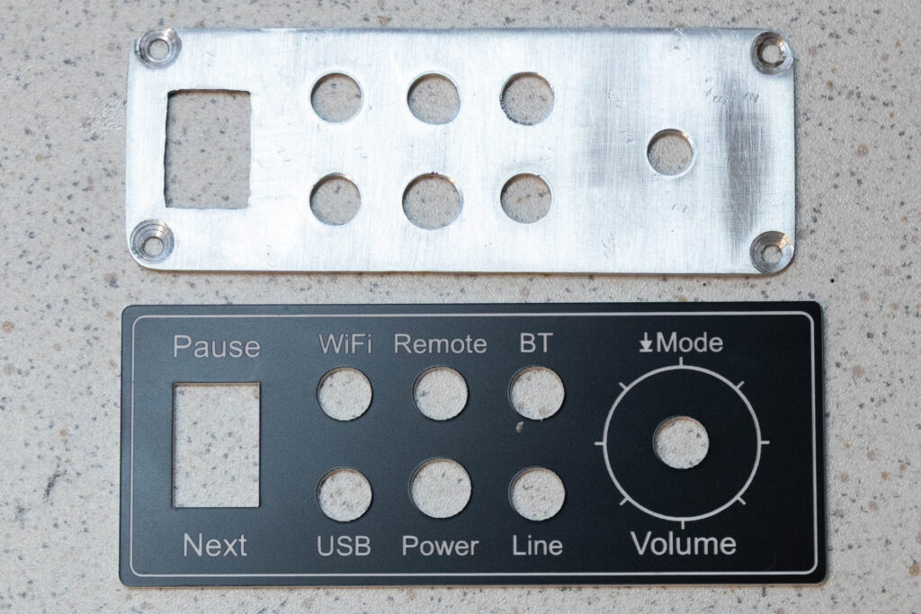
- The panel is made of 2mm Aluminum so that it fits exactly into the recess.
- Holes are drilled into the panel both for fastening screws and the elements that have to be mounted on the panel.
- A cover plate is made for each panel that is 2.5mm wider than the aluminum panel. It is made of 1.5mm Transply (a 2-layer ABS material). The holes for the elements are cut into the Transply and the necessary labels and scales are laser-engraved.
- The aluminum panel is screwed into the recess. The cover plate is positioned on top of the panel. The control elements, indicators, and input ports are mounted through the cover plate and the panel.
The main challenge was to design the panels so that they could hold all required elements while still being as small as possible. Usually, I needed 3-4 design iterations per panel until I reached a satisfactory solution. For example, these were the iterations for the control panel:
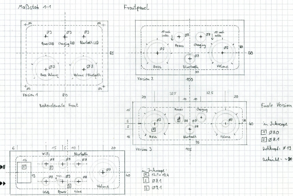
Control Panel
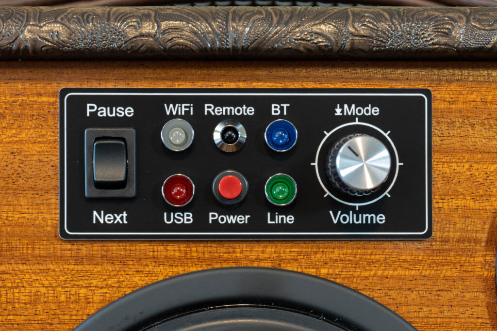
The control panel on the front of the cabinet has to carry the following elements:
- A Play/Pause and Next Track button.
I combined both functionalities by using a single rocker switch with (ON)-OFF-(ON) positions. - A Power/WPS button.
This is a simple push button. - An infrared (IR) sensor.
This sensor allows to use an IR remote control to control the boombox. I used an LED-shaped 5mm sensor with 38kHz frequency and 940nm wavelength (OS-0038N). - Four 3mm LEDs with metal housing.
These LEDs indicate the active input source (Bluetooth, WiFi, Line-In, USB). In hindsight, it would have been a better choice to use just one multi-color LED for this. - A volumn control and a mode button.
The volumn control is not a potentiometer but instead a digital encoder that generates Volume+ and Volume- pulses for the amplifier when it is turned. I used an ALPS-STEC11B encoder that generates 15 pulses per full turn. This encoder can also act as a button when its knob is pushed down. I used this additional functionality to realize the mode button that switches between input sources.
The aluminum panel has the dimensions 105x40mm. The corresponding cover plate has the dimensions 110x45mm.
Input Panel
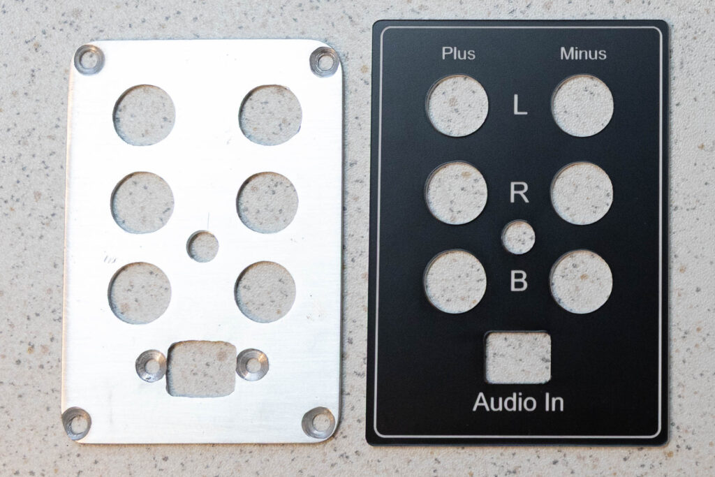
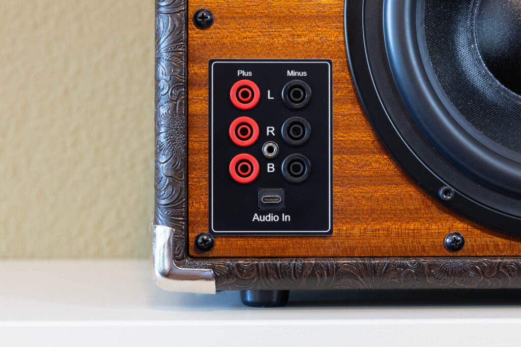
The input panel on the back of the cabinet has to carry the following elements:
- A USB-C port.
This port can be used to receive digital audio signals from a PC. The PC considers the boombox as an external sound card. This port is active when the input mode is switched to ‘USB’. - A 3.5mm jack socket.
This socket can be used to receive analog audio signals from any appropriate audio device (expecting 1Vrms = 0dBV). The socket is active when the input mode is switched to ‘Line-In’. - Six 4mm safety sockets for banana plugs.
This sockets can be used to send amplified audio signals directly to the individual speakers of the boombox (two fullrange speakers, one subwoofer). To not interfere or even damage the internal amplifier, this sockets are only active when the boombox is switched off. In this case, the speakers are galvanically isolated from the amplifier using relays. The rationale behind this special functionality is the secondary use of the boombox as “passive” speaker for testing HiFi equipment in the workshop.
The aluminum panel has the dimensions 80x55mm. The corresponding cover plate has the dimensions 85x60mm.
The Power Supply Panel
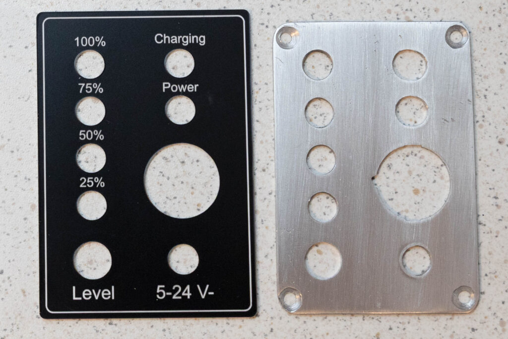
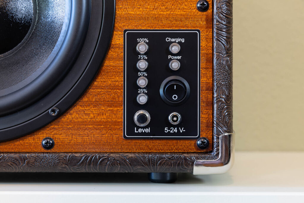
The power supply panel on the back of the cabinet has to carry the following elements:
- A power switch.
This switch connects/disconnects the amplifier from the power suppy. Charging of the batteries is still possible when the switch is off. - A charging socket 2.5×5.5mm DC coax.
The battery board uses a charging socket of 2.1x5.5mm. However, the 2.5x5.5mm size seems to be more common for notebook chargers here in Europe. Therefore, I used the latter size for the socket. This way, it will be easier to find a matching charger if the current one gets lost or breaks. - A power LED.
This LED indicates if external power is present. When the boombox runs on its batteries and the external charger is not plugged in, the LED is off. - A charging LED.
This LED indicates if the external charger currently charges the batteries. When the charger is not plugged in or the charging process has finished, the LED is off. - Four battery status LEDs and a test button.
These LEDs indicate the current charge level of the batteries (25%, 50%, 75%, 100%). They are only active when the test push button is pressed.
LEDs, button, and the corresponding pre-assembled cables and plug are part of an optional accessory pack for the Dayton Audio LBB-5S battery board (part ID LBB-5CL).
The aluminum panel has the dimensions 80x55mm. The corresponding cover plate has the dimensions 85x60mm.
In the next post, I will describe the final assembly steps of the boombox.