Definition and Purpose
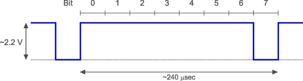
Most of the signal transmission within the camera is carried out serially over single lines. The SYNC signal (sometimes also called “synchronization trigger” or “D7”) defines the period in which one word (8 bits) is transmitted. It is a rectangular (pulse) wave with a duty cycle of 87.5% (= 87.5% high/on, 12.5% low/off). It has a nominal frequency of 212 = 4,096 Hz that is derived from the CLK signal by dividing by 8. This results in a period length of about 240 µsec. The transmission of a word starts when the SYNC signal switches from low to high (start of period) and ends when the signal switches from low to high for the next time (end of period). Usually, the transmission of the word is repeated in each period as long as the shutter release button is half-pressed. The SYNC signal itself can be interpreted as the transmission of the word 11111110. The amplitude of the signal is about 2.2 V. The signal is generated by the Decoder/Driver chip and provided at its pin 6*.
(* Canon’s service manual says pin 17 but this seems to be a pin numbering error. Following the standard rule that numbering is done counter-clockwise starting with the top-left pin, the pin number is 6. Canon seemed to have started the numbering at the bottom-right pin.)
The SYNC signal is essential both for the functioning of the camera and for the interpretation of transmitted words during troubleshooting. In the latter case, the signal is used to define trigger conditions for the oscilloscope when measuring other serial signals.
The Measurement
Test Point
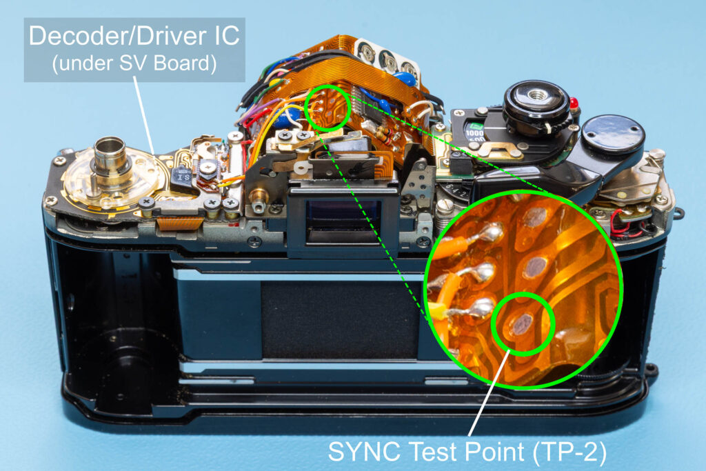
The SYNC signal can be measured at the SYNC test point, also called test point 2 or TP-2. This test point is on the top side of the main flexible board, left of the viewfinder edge.
Oscilloscope Settings
I suggest the following oscilloscope settings (all for Channel 1):
- DC coupling of the test probe
- horizontal scale (time base) 50 µsec/div
- vertical scale 500 mV/div, moved down by 1 V (= 2 div)
- DC-coupled trigger on Channel 1, mode ‘Auto’, rising edge at level 1 V
Connect the test probe of Channel 1 to test point TP-2.
Measurement
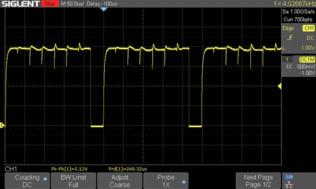
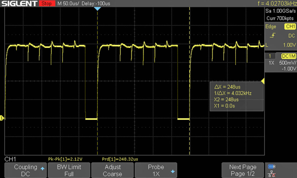
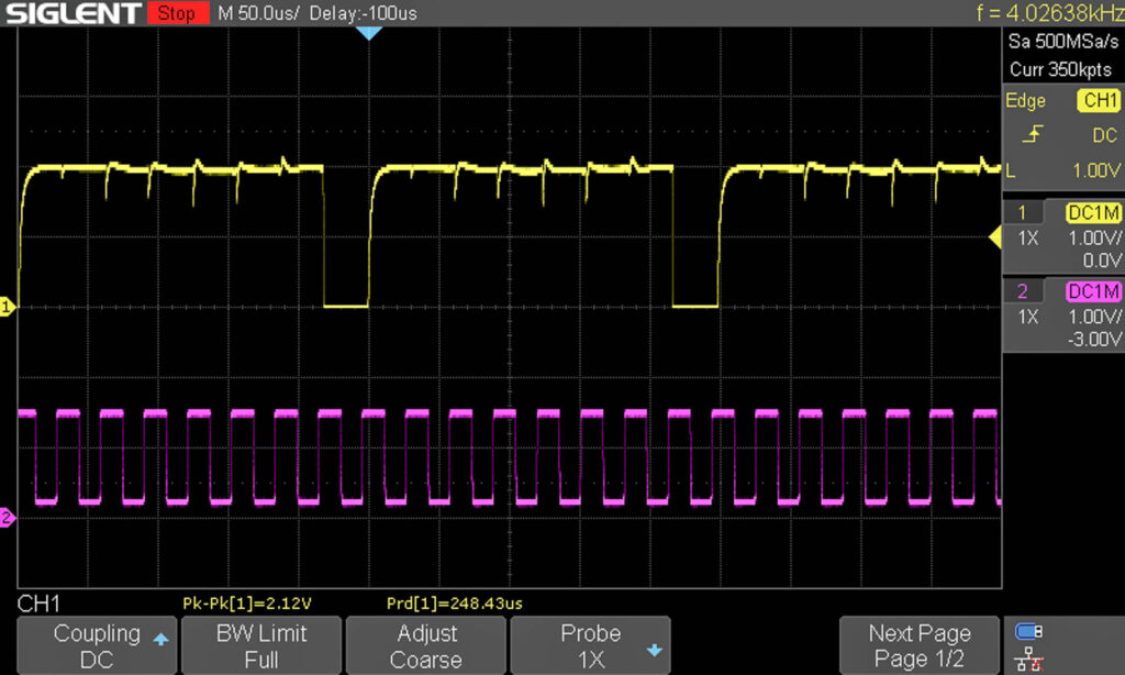
As can be seen, the camera has a healthy SYNC signal with an amplitude of 2.12 V, a frequency of 4,027 Hz, and a period length of 248 µsec. The frequency is a tiny bit slow (nominal value: 4,096 Hz) and the period length is a tiny bit high (nominal value: 244 µsec) but both are well within specs. For another camera, I measured an amplitude of 2.30 V, a frequency of 4,191 Hz, and a period length of 238 µsec.
For technical reasons, the SYNC signal shows some spikes in its high phase. From a transmission perspective, each spike can be interpreted as the end of the transmission of one bit.
Possible Errors
Signal Missing
If the signal is missing completely, check first if the power supply of the camera works correctly as well as the shutter release button. For example, half-press the shutter release button and check if the viewfinder display is working. If yes, both power supply and shutter release button should be OK.
Then, check if the CLK signal is available and looks OK (see this blog post for details).
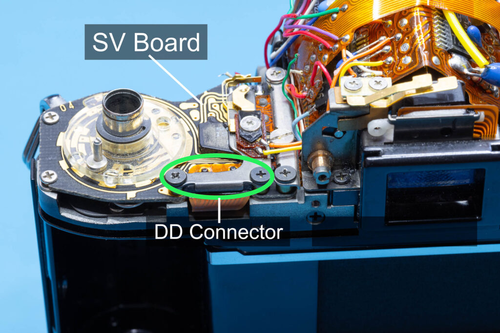
Then, check if the DD (‘Decoder Driver’) connector on the SV circuit board makes good contact. If in doubt, remove the connector plate (two screws) and clean the contacts on the SV board and the flexible board.
Otherwise, the Decoder/Driver chip might be broken.
Incorrect Signal Waveform
If the waveform of the signal is incorrect (not a rectangular wave, duty cycle other than 87.5%, significant voltage deviations), the Decoder/Driver chip might be broken.
Incorrect Frequency
The SYNC signal is derived from the CLK signal. Usually, an incorrect frequency of the SYNC signal means that the frequency of the CLK signal is off. Canon states that a frequency range of 30,117 Hz (-8%) to 34,134 Hz (+4%) of the CLK signal is OK. Accordingly, a frequency range of 3,764 Hz to 4,266 Hz (period length of 234 µsec to 265 µsec) of the SYNC signal is considered OK. If the SYNC signal is outside this range, you may have to adjust the frequency of the CLK signal as described in this blog post.
Preparation for Further Signal Measurements
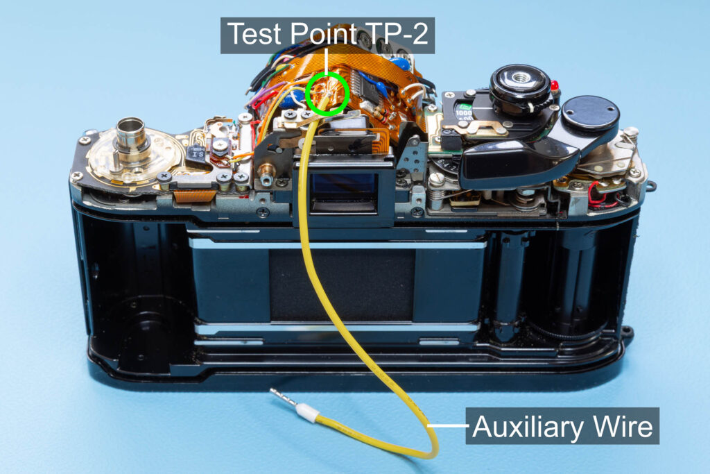
As already said, the SYNC signal is essential for the interpretation of words transmitted via other signals. Therefore, when you use an oscilloscope to visualize and interpret these signals, you also have to feed the oscilloscope with the SYNC signal (on the second channel). This way, it can be used as a trigger and can also be displayed on the screen as auxiliary trace. To achieve this, you need two test probes that you have to put onto two different test points, the test point for the measured signal and the test point TP-2 for the SYNC signal. This can be quite difficult with only two hands. Therefore, my suggestion is to solder a piece of wire to the SYNC test point TP-2 and grab its other end with the second test probe to free one hand. As always, be careful when soldering to not destroy the flexible board or damage the camera by static discharges (use ESD protection).