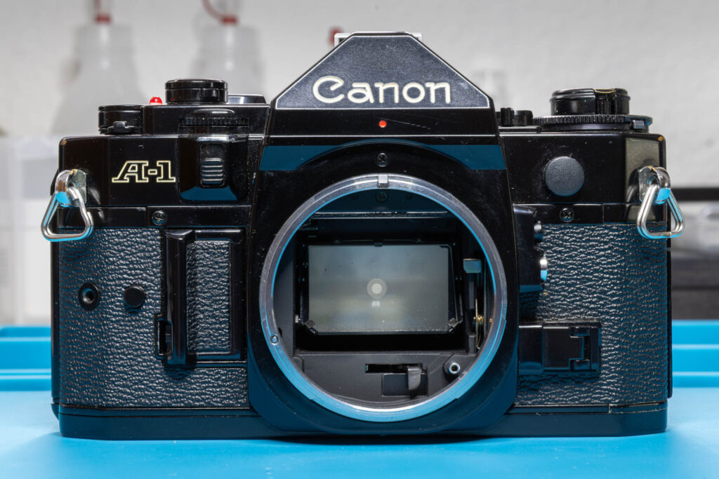
Definition and Purpose
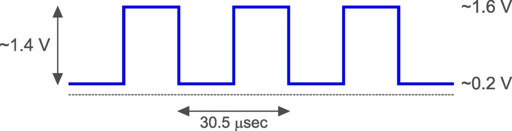
The CLK signal (sometimes also called “CLOCK signal”) can be considered as the “heartbeat” of the camera. It provides the common time base for all electrical functions of the camera, like metering, shutter control, and viewfinder display. It synchronizes the operation of the integrated circuits of the camera and the communication between them. The CLK signal is a square wave with a duty cycle of 50% (= 50% high/on, 50% low/off). It has a nominal frequency of 215 = 32,768 Hz. Its amplitude is about 1.4 V, with high level about 1.6 V and low level about 0.2 V.* The signal is generated by the OSC/Interface chip and provided at its pin 15.
(* Own measurements. Canon’s service manual specifies 1.0 V to 1.2 V for the high level and 0.0 V to 0.1 V for the low level.)
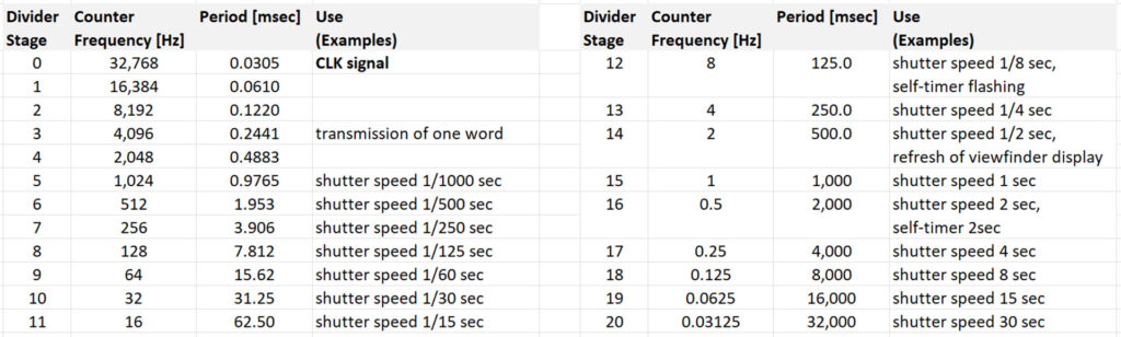
The camera contains a 20-stage divider/counter for the CLK signal to derive all important timings for its operation. Each stage divides the frequency of the previous stage by 2.
The Measurement
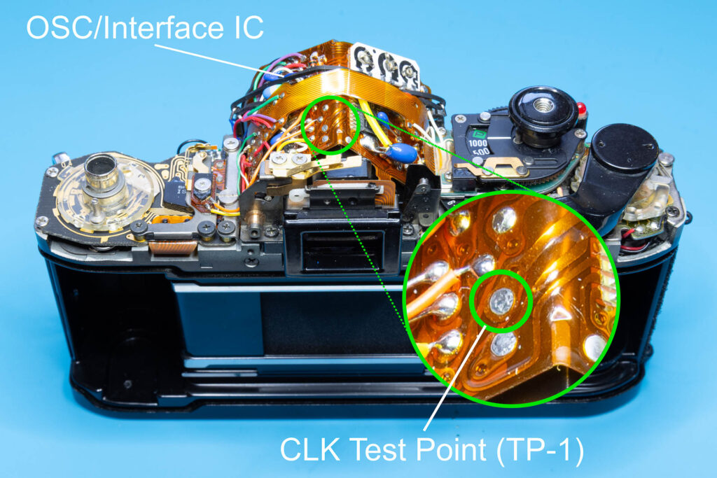
Test Point
The CLK signal can be measured at the CLK test point, also called test point 1 or TP-1. This test point is on the top side of the main flexible board, left of the viewfinder edge.
Oscilloscope Settings
I suggest the following oscilloscope settings (all for Channel 1):
- DC coupling of the test probe
- horizontal scale (time base) 10 µsec/div
- vertical scale 500 mV/div, moved down by 1 V (= 2 div)
- DC-coupled trigger on Channel 1, mode ‘Auto’, rising edge at level 1 V
Connect the test probe of Channel 1 to test point TP-1.
Measurement
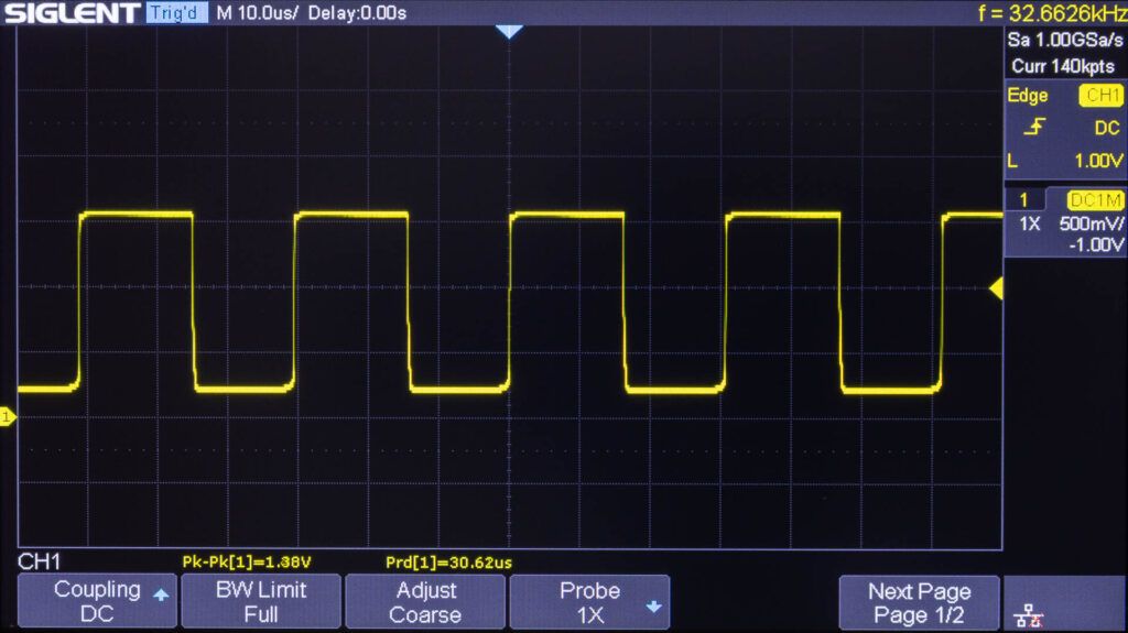
As can be seen, the camera has a very healthy CLK signal with an amplitude of 1.38 V and a frequency of 32,663 Hz. The frequency is only 0.3% slow compared to the nominal frequency of 32,768 Hz. Here are the results for two other cameras:
- Amplitude of 1.42 V and frequency of 33,520 Hz (2.3% fast).
- Amplitude of 1.36 V and frequency of 32,191 Hz (1.8% slow).
Possible Errors
Signal Missing
If the signal is missing completely, check first if the power supply of the camera works correctly as well as the shutter release button. For example, half-press the shutter release button and check if the viewfinder display is working. If yes, both power supply and shutter release button should be OK.
Then, check if there is continuity between the test point TP-1 and pin 15 of the OSC/Interface chip. If not, there is probably a broken trace on the main flexible board.
Otherwise, the OSC/Interface chip might be broken.
Incorrect Signal Waveform
If the waveform of the signal is incorrect (not a square wave, duty cycle other than 50:50, significant voltage deviations), the OSC/Interface chip might be broken.
Incorrect Frequency
Although the nominal frequency of the signal is 32,768 Hz, Canon states that a frequency range of 30,117 Hz (-8%) to 34,134 Hz (+4%) is OK. If the measured frequency is outside this range, it should be adjusted. Adjustment is done by replacing resistor Rosc with a different one from the range of 115 kiloohm to 162 kiloohm. In my camera, the value is right in the middle at 140 kiloohm. Resistor Rosc connects pin 9 of the OSC/Interface chip with pin 17 of the CPU chip. It is located to the right of the OSC/Interface chip, underneath the AT flexible board. To replace it, you first have to disconnect the AT flexible board from the SV circuit board (to reach the resistor). Then, you can desolder Rosc from the main flexible board and try another resistor value from the range described above. Canon suggests to use a variable resistor of 200 kiloohm first to determine the resistance value that produces the correct frequency and then install a resistor with (about) this value.