Tools
The Oscilloscope
As the title of this series of blog posts implies, you need an oscilloscope. Although some of the easier measurements can also be made with an oscilloscope that has only one channel, my suggestion is to use one with at least two channels. Often, it helps to display a second, auxiliary trace to help interpret the main trace. Both analog and digital oscilloscopes should work for most of the tasks (after all, the repair technicians back then only had analog oscilloscopes). However, I suggest to use a digital storage oscilloscope (DSO) with a decent memory depth. Some of the signals in the Canon A-1 are transmitted only occasionally without an easy-to-use trigger event. For these signals, it might be necessary to store a longer trace and then search for the occurrence of the signal. The oscilloscope should have a decent-sized screen with a good resolution since certain traces contain quite some information that could be hard to identify otherwise. The bandwidth of the oscilloscope is practically irrelevant, even simple models with only 1 MHz bandwidth should be sufficient.
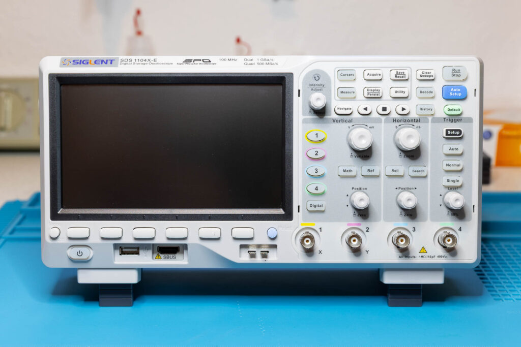
I personally use a mid-tier oscilloscope, the Siglent SDS 1104X-E. It is a digital storage oscilloscope with four channels, a bandwidth of 100 MHz, and a memory depth of 14 Mpts (million sample points). The screen size is 7″, the resolution is 800×480, the display grid is 8×14 divisions. Much more powerful than needed.
The Power Supply
To perform measurements with an oscilloscope, the Canon A-1 has to be switched on (main switch set to ‘A’), the shutter release button has to be either half-pressed (metering mode) or full-pressed (shutter-release mode), and the camera has to be supplied with sufficient voltage (about 5.7 V to 6.3 V). For the latter, you can just power the camera via its usual battery (PX28 replacement, like a 4LR44). However, I decided to build a DIY battery adapter and use my bench power supply instead. This has two advantages: First, you can set a current limiter and display the actual current (if the power supply supports these features). Second, you do not drain the battery (that should be rather used to take photos 😉).
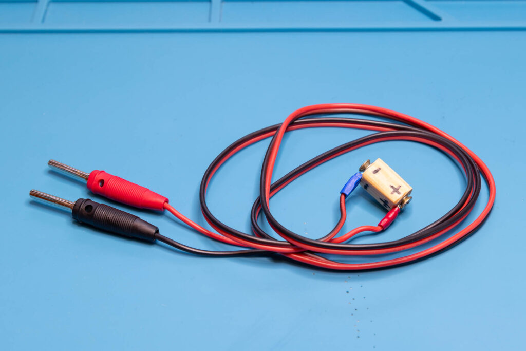
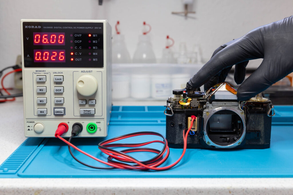
Be careful when using such adapter / bench power supply combination:
- Do not reverse the voltage polarity!
- When both your oscilloscope and your bench power supply are mains-powered and the ‘Minus’ post of the power supply is connected to earth, never connect the ground (“alligator”) clip of your test probe to something other than the ground (typically, the chassis) of the camera! Otherwise, you may damage the camera or your oscilloscope. For details, see this educational video: EEVblog #279 – How NOT To Blow Up Your Oscilloscope!
- If the power supply has a current limiter, set it to a value of 100mA. This will reduce the risk of damaging the camera in case you produce a short-circuit accidentally.
Soldering Equipment
Sometimes, you need to display two signals at once on the oscilloscope or use a second signal as a trigger. In most cases, it is impossible to use a test probe with a hook tip (“mini-grabber”) since there is no component or post on the circuit boards of the Canon A-1 to hook it to. Instead, you have to use a pointed tip and press the tip against a flat test point on the circuit board. Since you also have to half-press the shutter-release button for a measurement, you can run out of hands quickly. Therefore, it might be necessary to temporarily solder a wire to a test point so that you can connect a hook tip to the other end of the wire (saves one hand 😉).
I will not give detailed advice on the soldering equipment you should use. Its the same equipment you would also use when disassembling the camera. In best case, you have a temperature-controlled soldering iron with a small tip.
Preparation
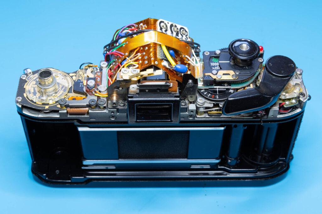
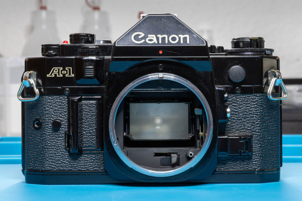
First, follow the procedure described in this blog post to remove the top cover of the Canon A-1. Then, reassemble the shutter button and the film advance lever. Afterwards, your camera should look like this: