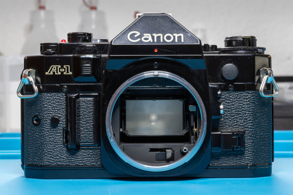
Definition and Purpose
The user sets the exposure mode (Tv – time value or shutter priority, Av – aperture value or aperture priority) on the AE mode selector of the camera. Then, the user sets the concrete value of the exposure mode (Tv: shutter speed, Av: aperture) on the AT dial. The camera transmits the combination of both information as a six-bit Gray code via parallel lines to a diode array. Reusing multiplexer signals of the Decoder/Driver chip (primary intended to multiplex the digits of the viewfinder display), the diode array transforms the parallel signal into a serial signal called the T/A signal (time/aperture). This signal is then sent to the CPU chip for further processing, especially to calculate the shutter speed / aperture combination to be used. The signal repeats the transmission of the same word as long as the user half-presses the shutter release button and does not change the exposure mode or the exposure value. The amplitude of the signal is about 2.2 V.
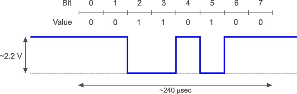
(Consider that the Canon A-1 uses the “active low” logic where value ‘1’ of a bit is represented by a low voltage while value ‘0’ is represented by a higher voltage.)
The Gray code of the T/A signal looks like this (first five bits: value of exposure mode, sixth bit: exposure mode – Tv = 0, Av = 1):
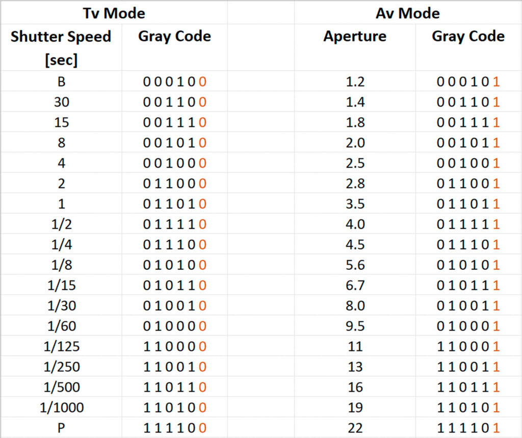
(In the table above, the values of the Gray code are denoted in “least significant bit first” mode.)
Since the Gray code of the T/A signal is only six bits long but the length of transmitted words is always eight bits, a prefix of two ‘0’ padding bits is added. For example, the word 00110000 represents exposure mode Tv with a shutter speed of 1/125 sec and the word 00110001 represents exposure mode Av with an aperture of f11.
The Measurement
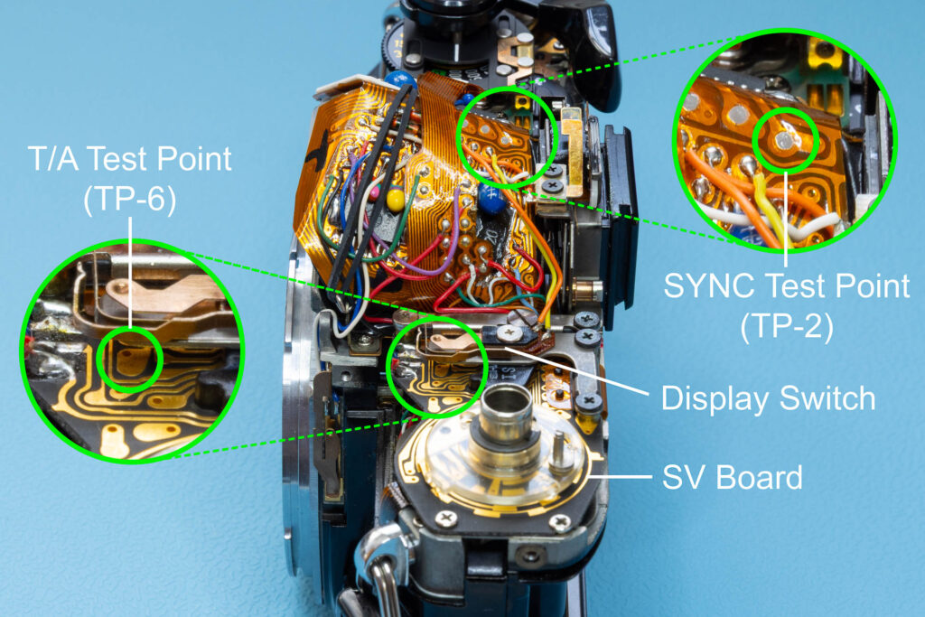
Test Point
The T/A signal can be measured at the T/A test point, also called test point 6 or TP-6. This test point is on the SV circuit board, partly hidden under the display switch (SW3). Unfortunately, the display switch cannot be removed for better access to the test point since the switch assembly also acts as connector plate for the flexible board leading to the Decoder/Driver chip. Therefore, you have to be careful when connecting the test probe to not cause short circuits. Best way is to tilt the test probe to reach under the display switch without touching it.
To use the SYNC signal as trigger, you have to connect a second test probe to TP-2.
Oscilloscope Settings
I suggest the following oscilloscope settings (all for Channel 1):
- DC coupling of the test probe
- horizontal scale (time base) 50 µsec/div
- vertical scale 500 mV/div, moved up by 1 V (= 2 div)
- signal trace inverted*
- DC-coupled trigger on Channel 2, mode ‘Auto’, rising edge at level 1 V
(* For easier interpretation of the transmitted word. Reason is the “active low” logic of the camera where value ‘1’ of a bit is represented by a low voltage while value ‘0’ is represented by a higher voltage.)
Connect the test probe of Channel 1 to test point TP-6. Connect the test probe of Channel 2 (used as trigger) to test point TP-2.
Measurement
Assume you perform a measurement with the settings described above and get the following trace displayed on the oscilloscope:
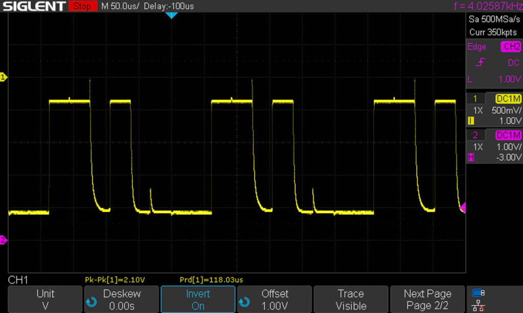
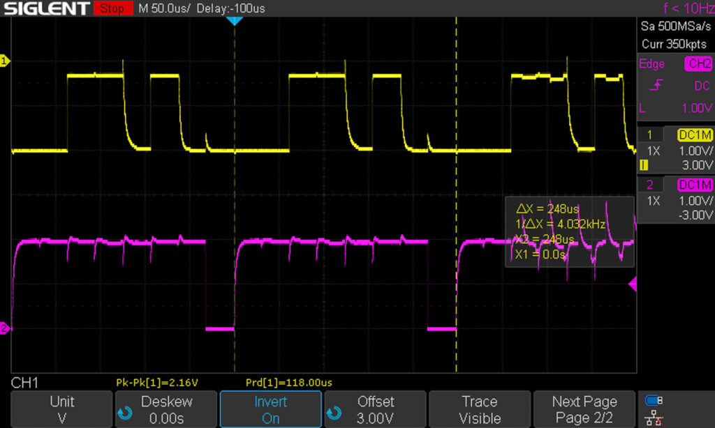
How to interpret this trace? Quite simple: Take the five horizontal divisions following the trigger point (on my oscilloscope marked by a blue triangle), divide this area into eight equal segments, and note down a ‘0’ or ‘1’ (for a low/high value of the trace) for each of these segments. Each segment represents one bit of the transmitted word.
If your oscilloscope has a ‘Cursor’ function it will help to define an X (time) cursor that starts at the trigger point and has a length of about 240 µsec. Then, the start and end of the cursor mark the area that you have to divide into the eight segments.
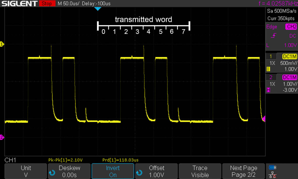
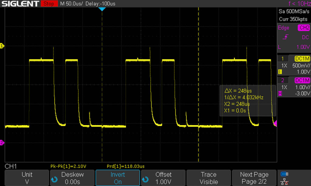
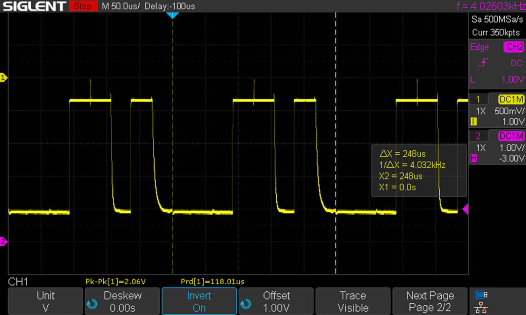
For the trace displayed above, this results in the word 00110100. As already explained, the first two bits (’00’) are just padding bits and have to be removed to get the actual Gray code value. This leaves us with the bit sequence 110100. Looking it up in the Gray code table contained in the first chapter, we learn that it represents exposure mode Tv with a shutter speed of 1/1000 sec. Here are some more measurements for other T/A signal values:
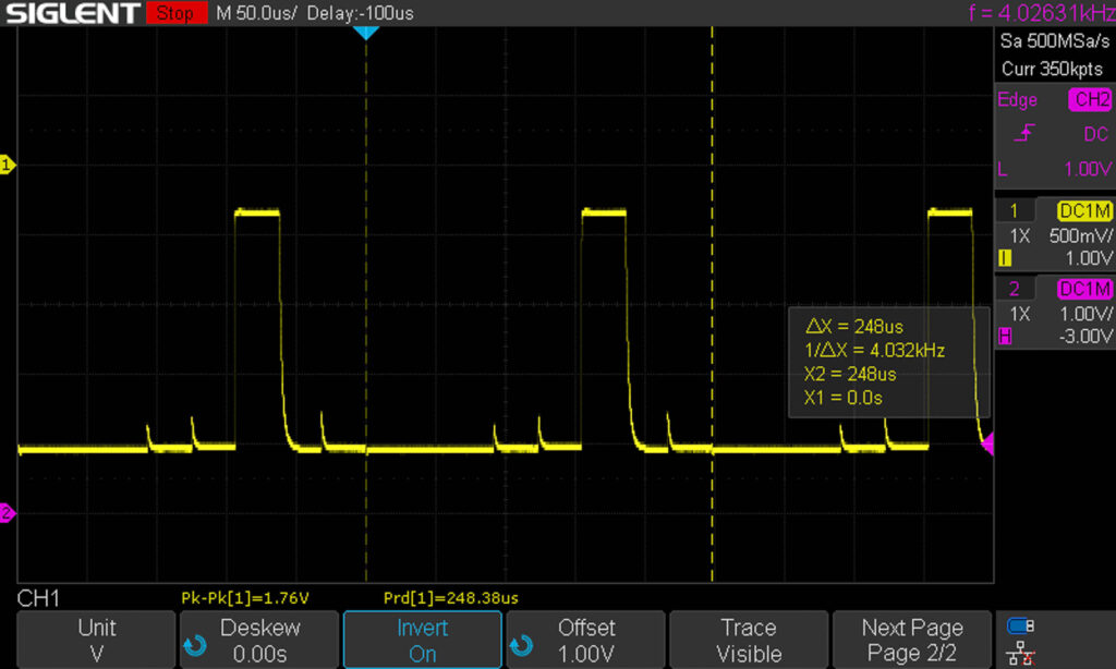
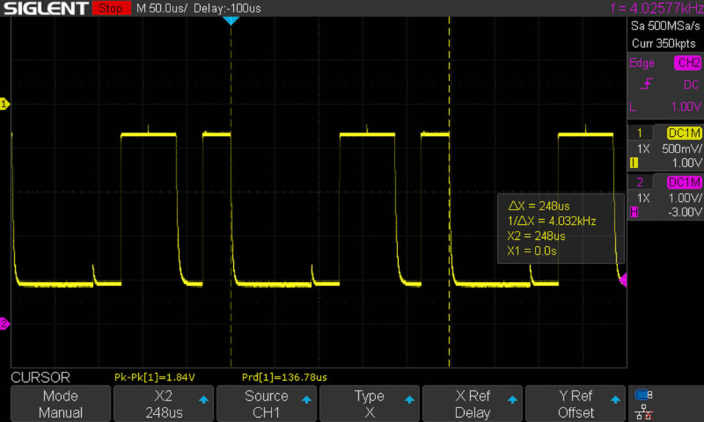
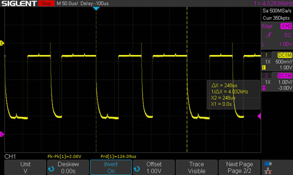
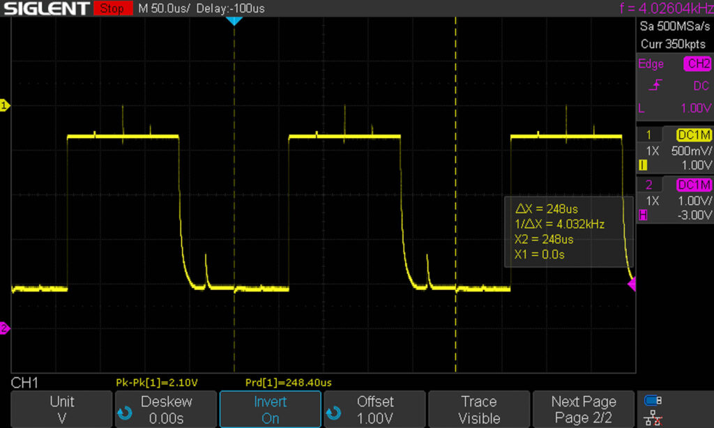
To illustrate the relation between the T/A signal and the SYNC signal (the raising edge of the SYNC signal marks the beginning of a transmitted word of the T/A signal), the following screenshot displays both signals for exposure mode Tv with 1/1000 sec:
Possible Errors
Signal Missing
If the signal is missing completely, check first if the power supply of the camera works correctly as well as the shutter release button. For example, half-press the shutter release button and check if the viewfinder display is working. If yes, both power supply and shutter release button should be OK.
Then, check if the SYNC signal is available and looks OK (see this blog post for details).
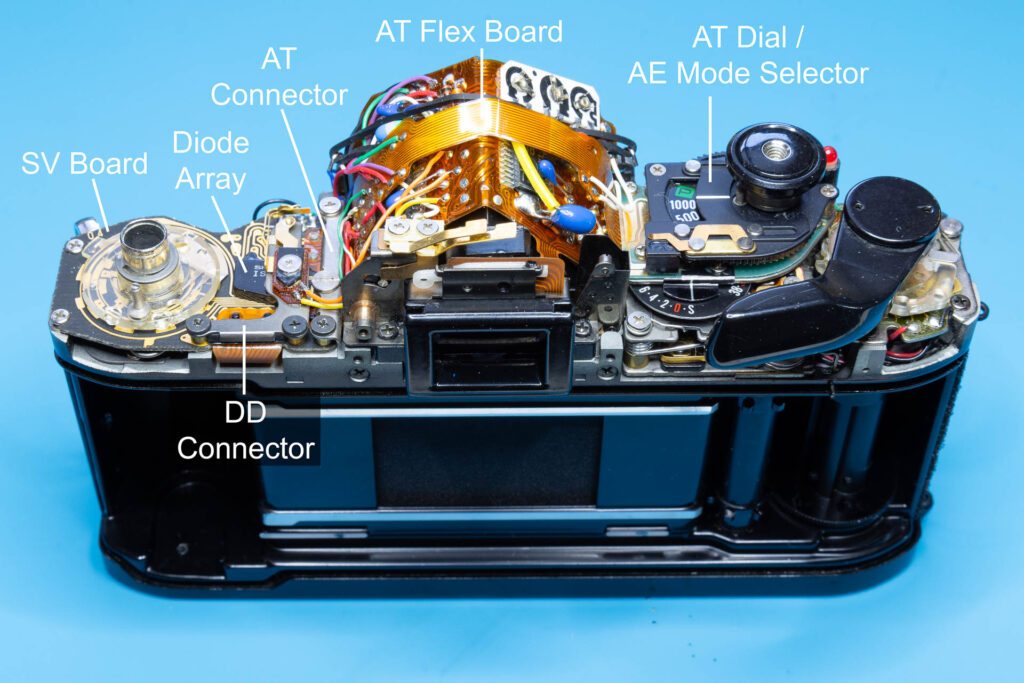
Otherwise, the connection from the AT dial to the diode array (six parallel traces on the AT flexible board) might be broken, the AT connector might not make good contact, or the diode array on the SV board might be broken.
Incorrect Word is Transmitted
In most cases, an incorrect word is caused by one or multiple “broken” bits that are either always ‘0’ or always ‘1’ regardless of the settings you made on the AE mode selector or the AT dial. For example, if the seventh bit of the word is always ‘0’, you will see a shutter speed of 1/1000 sec when you have set 1/500 sec and you will see 1/125 sec when you have set 1/250 sec. Another example: If the eighth bit is always ‘0’, the camera will behave as if it was in exposure mode Tv even if you set the mode to Av.
Probably, this behavior is caused by one of the following causes of error:
- A contact surface of the AT dial is corroded or the corresponding wiper contact is bent or broken.
- A trace of the AT flexible board is broken or the corresponding contact of the AT connector is corroded.
- A diode of the diode array is defective.
- A contact of the DD connector is corroded.
- An output port of the Decoder/Driver chip is defective.
(The first cause of error can occur when you disassembled and reassembled the AT dial during a repair. One or more of the tiny wiper contacts can be bent easily in the process.)