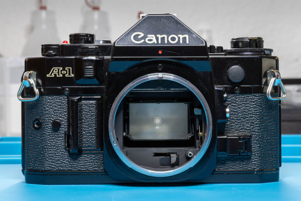
The Camera
The use of an oscilloscope for troubleshooting requires the camera electronics to be supplied with power. That means that you have set the camera’s main switch to ‘A’ and you have pressed one of the following buttons:
- the shutter release button (half-pressed: metering mode, full-pressed: shutter release mode)
- the battery check button
- the exposure preview button
- the exposure memory button
Which button you have to press depends on which measurement you want to perform. For the most scenarios described here, you have to half-press the shutter release button. In this case, you could screw a threaded, locking shutter release cable into the shutter release button and fix it at the half-pressed position. This will save you one hand during the measurements. However, this can drain the battery of the camera more quickly so that the use of an external power supply is recommended.
Furthermore, measurements can only provide meaningful results if the circuitry of the camera is not disassembled. Especially, this means that you did not remove the mirror box or the flexible board connectors and have not desoldered any wires (except for the flash sync wire).
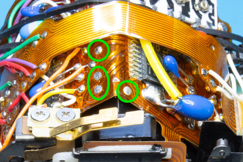
The Canon A-1 uses double-sided circuit boards, both solid and flexible ones. Often, it is not possible to reach the bottom side of the boards without disassembling the camera partially. Even reaching components on the top side of the boards might not be easy due to overlapping boards or tiny contacts. Therefore, Canon added a number of so-called “test points” (small metallic pads) in easily accessible areas on the top side of the boards. Each test point provides access to a specific signal. For identification of the test points, I will use the numbers specified in the C&C Associates article Electronic Troubleshooting the Canon A-1 (TP-1, TP-2, etc.).
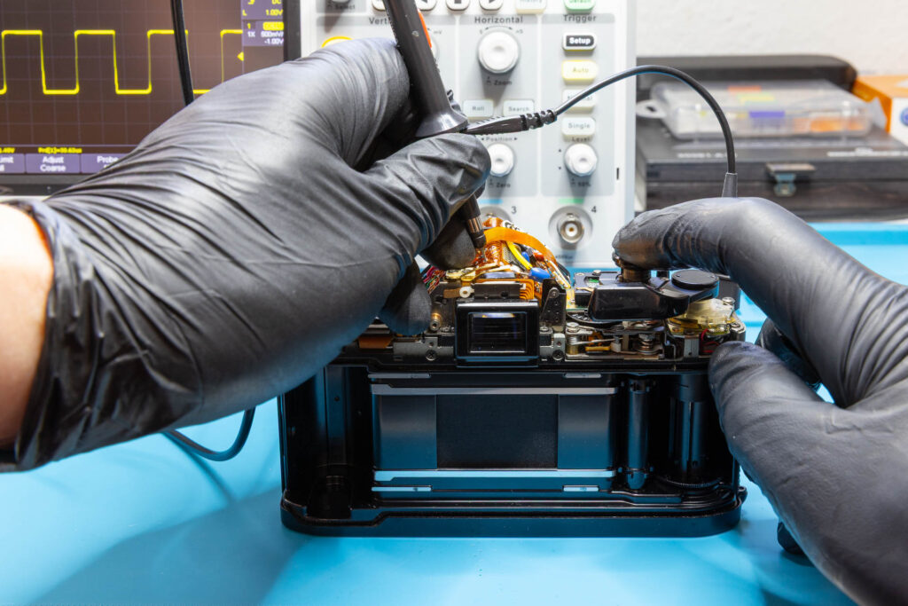
The Oscilloscope
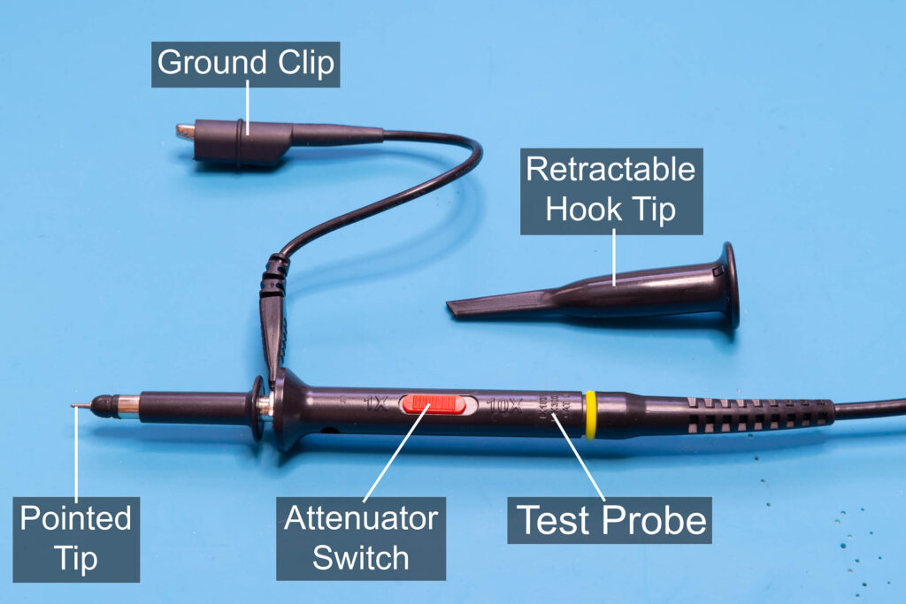
To perform the measurements, you have to connect the ground (“alligator”) clips of all test probes you use to the electrical ground of the camera. Since the electrical ground is connected to the chassis of the camera, you can attach the ground clips to any location on the chassis where the bare metal is exposed. For ease of use, I always use the strap lugs on both sides of the chassis. Then, you either press the pointed tip of the test probe directly onto the respective test point or use a hook tip and attach it to the wire you have soldered to the test point. The latter can be necessary if you want to measure multiple signals at once.
Usually, your test probes will have an attenuator switch where you can switch between “1x” and “10x”. For measurements in the Canon A-1, you can set the switch to “1x” since the voltage is small (≤ 6 V), the signal frequencies are low (≤ 32 kHz), and the signals are strong. Set the coupling mode of the test probes to “DC coupling”. This mode lets both the DC and AC components of the signal pass through to the oscilloscope, allowing to measure the voltages of the signal against ground. This is necessary because variations in signal voltage can indicate circuit errors.
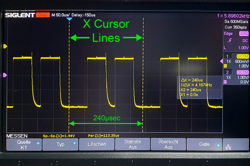
For most measurements, the optimal horizontal scale (time base) is 50 µsec/div (“div” = division = length of one square of the display grid). Typically, an oscilloscope has 10 horizontal divisions (mine has 14). At 50 µsec/div, the oscilloscope displays signals over a time period of 10×50 µsec = 500 µsec (= 0.5 msec). This is sufficient to display about two words (each transmitted within 240 µsec) on the screen.
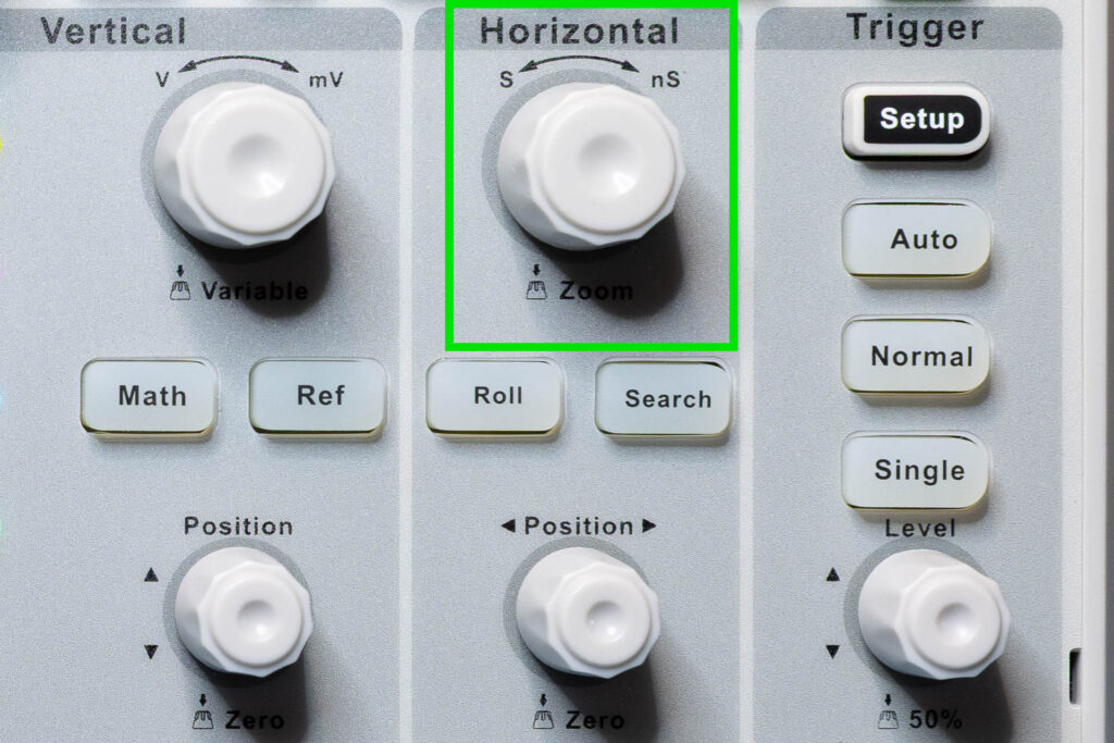
If your oscilloscope has a ‘Cursor’ function, you can set an X cursor with a width of 240 µsec. This will help to visualize one complete word displayed on the screen by marking its beginning and end.
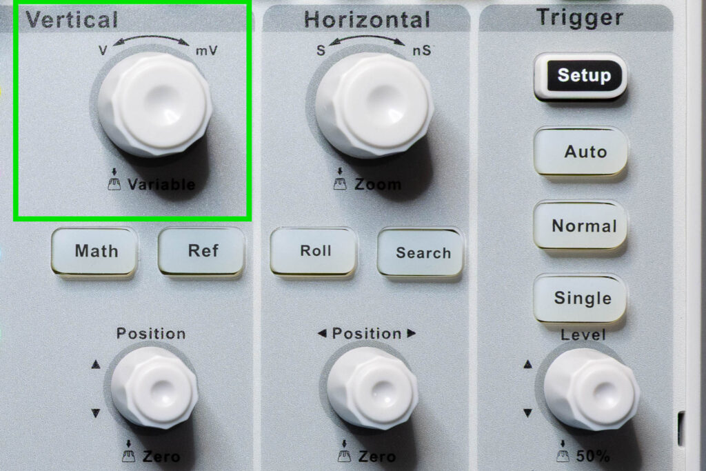
For most measurements, the optimal vertical scale (voltage scale) is 500 mV/div when you display one signal. Typically, an oscilloscope has 8 vertical divisions. At 500 mV/div, the oscilloscope can display a voltage range of 8×500 mV = 4 V. This is sufficient since most signals of the Canon A-1 are in the 1 V to 2 V range. If you want to display more than one signal non-overlapping, you might have to increase the vertical scale (for example, to 1 V/div).
As already explained in the Bits and Bytes blog post, it can be useful to invert the display of signal voltages to transform Canon’s “active low” logic to a more comprehensive “active high” logic virtually.
Alternative settings (other scales) or additional settings (like trigger conditions) might be needed when measuring specific signals. The concrete settings will be described in the blog posts dealing with the respective signals.