Some Definitions
A bit is the most basic unit of information in digital systems. It represents a logical state that can take on one of two possible values. It is common practice to denote these values as 0 and 1 but you could also think of them as no and yes or false and true. In computers and other electronic devices, the values are represented by different voltage levels (like 0 V and 5 V).
A byte is a unit of information consisting of eight bits (in the past, also other bit lengths were used). Each of the bits has a specific position within the byte, often denoted by numbers 0 to 7. There are two variants of assigning the bit positions to the position numbers: starting with 0 and ascending (also called “least significant bit first” or “LSB first”) or starting with 7 and descending (also called “most significant bit first” or “MSB first”). Usually, the latter one is used since it corresponds to the way we write numbers (“most significant digit first”).

A byte can be interpreted as a number in a base-2 system where each bit contributes with <bit value> x 2<position number>. For the byte shown above, this number (in decimal system) is 1×27 + 0x26 + 1×25 + 1×24 + 0x23 + 0x22 + 1×21 + 0x20 = 178.
A word is a unit of information consisting of a specific number of bits. In most cases, the concrete number (also called “word size”) depends on the architecture of the hardware on which the word is used. In most cases, it is defined by the number of bits the hardware can process in one step. For example, in a 32-bit CPU a word consists of 32 bits.
Usually, the order of binary numbers (bytes, words, etc.) is defined by their numerical values. As a result, at least one, but often multiple bits change from one binary number to its direct successor. If the binary numbers are set by a mechanical device (like a multi-layer rotary switch) this can result in the following problem: If switching from one binary number to the next requires changes of multiple bits (like 0111 -> 1000, three bits change) some of the bits might change earlier than others due to mechanical inaccuracies. In this case, the device can produce “transitional” numbers that might result in a hardware malfunction. For example, when switching from 0111 to 1000, the device might produce transitional numbers 0011, 0001, … before reaching the correct number 1000. To prevent such situations, the Gray code was developed in the 1940s. It is a binary code where the order of the binary numbers is changed so that only one bit changes from one binary number to the next. This way, no transitional numbers can occur since the device produces either the “old” binary number (before the bit changes) or the “new” binary number (when the bit has changed).
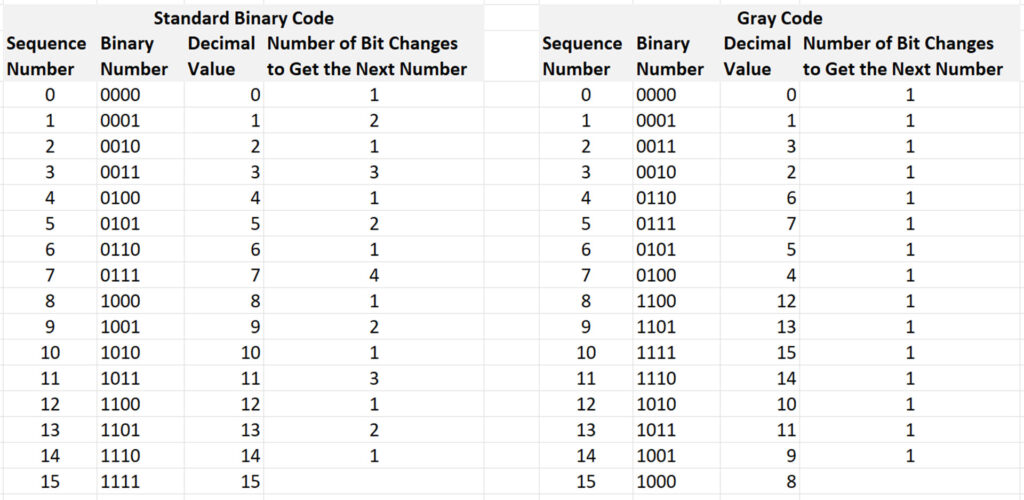
The Gray code shown above is the so-called “binary-reflected Gray code” that Frank Gray developed originally. However, for each unit of more than three bits there are multiple valid Gray codes with a different sequence of the binary values that fulfill the “change only one bit” property.
Representation in the Canon A-1
The Canon A-1 uses a 8-bit CPU that processes 8 bits at a time. Therefore, a word consists of 8 bits, allowing for representation of 256 values. Although this word size equals those of a byte I will still use the term “word” (not “byte”) in my posts since this term is also used in the repair documents. In cases where not the whole 8 bits are needed to represent a specific set of values, the least significant bits are filled with ‘0’. When processed, the bit order of a word is “MSB first”. However, when a word is transmitted serially the bit order is “LSB first” (for historic reasons). Since we can only observe words during transmission (not during processing inside the CPU), only the “LSB first” order is relevant for us. When you display the trace of a word on the oscilloscope, the least significant bit (LSB) will always be on the left side and the most significant bit (MSB) will always be on the right side of the screen. For ease of use, all concrete word values are also written in “LSB first” form, both in the repair documents and in my blog posts.
With a few exceptions, the Canon A-1 uses the “active low” logic where value ‘1’ of a bit is represented by a very small voltage (~0.0 V) while value ‘0’ is represented by a higher voltage (≥ 1.0 V). Depending on the concrete meaning of the word that contains the bit, the concrete voltage levels can vary due to technical reasons. Since “active low” is a bit counter-intuitive, it could lead to an incorrect interpretation of the oscilloscope trace. Therefore, it might be useful to invert the displayed trace (setting on the oscilloscope) to switch to the common “active high” logic virtually.

In the repair documents, Canon denotes the bits of a word with TB0 to TB7 (TB = “time bus”). TB0 is the least significant bit (transmitted first), TB7 is the most significant bit. The transmission of a complete word (TB0, TB1, …, TB7) takes 240 μsec (detailed explanation in a later post).