Disclaimer: In this post, I present a project that I finished successfully. However, it is not meant as a detailed construction manual. The description may be incomplete and might even contain errors. Feel free to use it as an inspiration for your own project but scrutinize the information presented here and use your common sense. Build at your own risk!
The power supply is a critical part of any boombox for two reasons: First, the achievable output power of the amplifier depends on the voltage/current provided by the power supply. Especially, a high output power (= strong power supply) is advantageous when playing bass-heavy music since the subwoofer requires a lot of energy. Second, the power supply has to be autonomous and portable. These are conflicting goals since a strong power supply can be quite heavy and an autonomous power supply (= batteries) is often not that strong and/or durable. Therefore, a compromise is necessary.
After some research, I decided on using five 18650 lithium batteries connected in series. This results in a maximum voltage of 5×4.2V = 21V (when fully charged) and an average voltage of 5×3.7V = 18.5V. I chose unprotected flat top Samsung INR-18650-30Q batteries with a capacity of 3000mAh. This should power the boombox with the given speakers and amplifier for about an hour at maximum volume (2x20W+40W) and at least five hours at moderate volume (2x4W+8W). To carry the batteries and provide protection and charging capabilities, I bought the Dayton Audio LBB-5S Battery Board. Beside other factors, I chose this board since it contains a battery management system (BMS) and there are useful accessories available (like external charging and battery status LEDs). The batteries and the board together weigh about 400g.
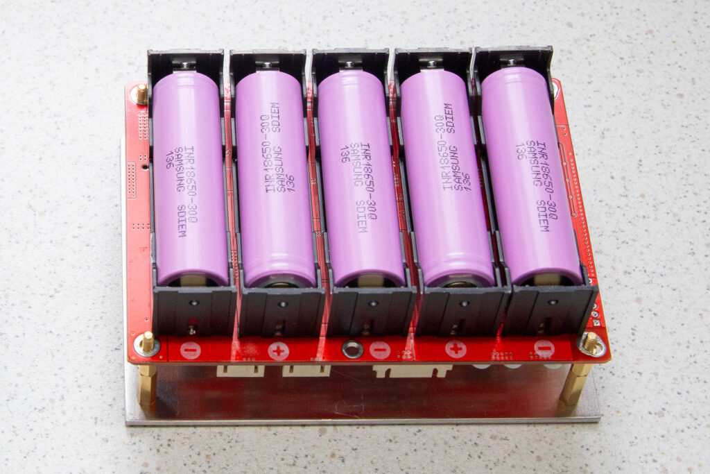
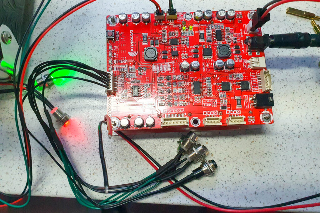
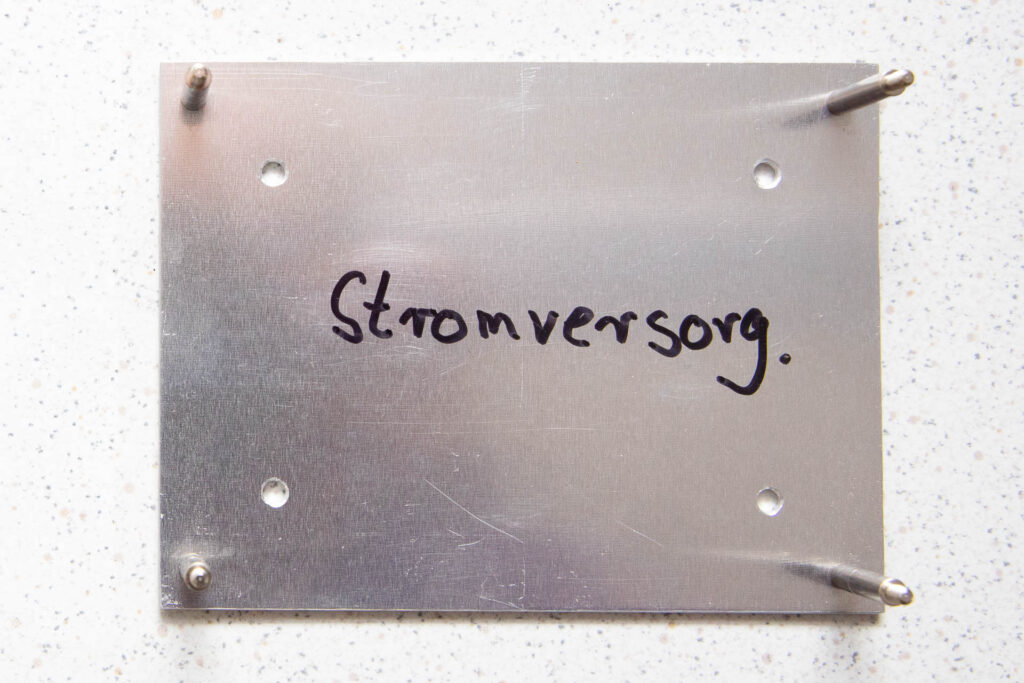
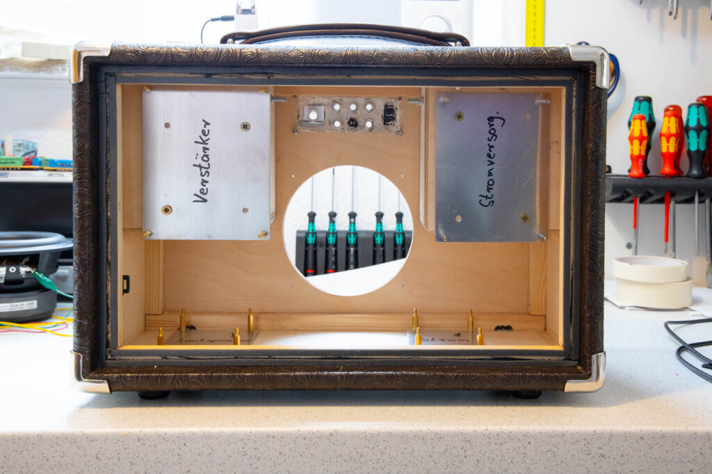
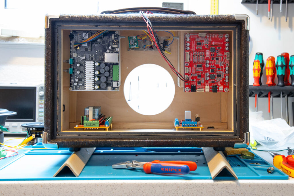
As for the amplifier, I made a base plate out of 2mm aluminum for easier installation. It has metal standoffs for the four mounting holes of the battery board. I screwed this base plate to the compartment of the left speaker (the right compartment when seen from the back). Then, I mounted the battery board to the base plate (with the connector side up).
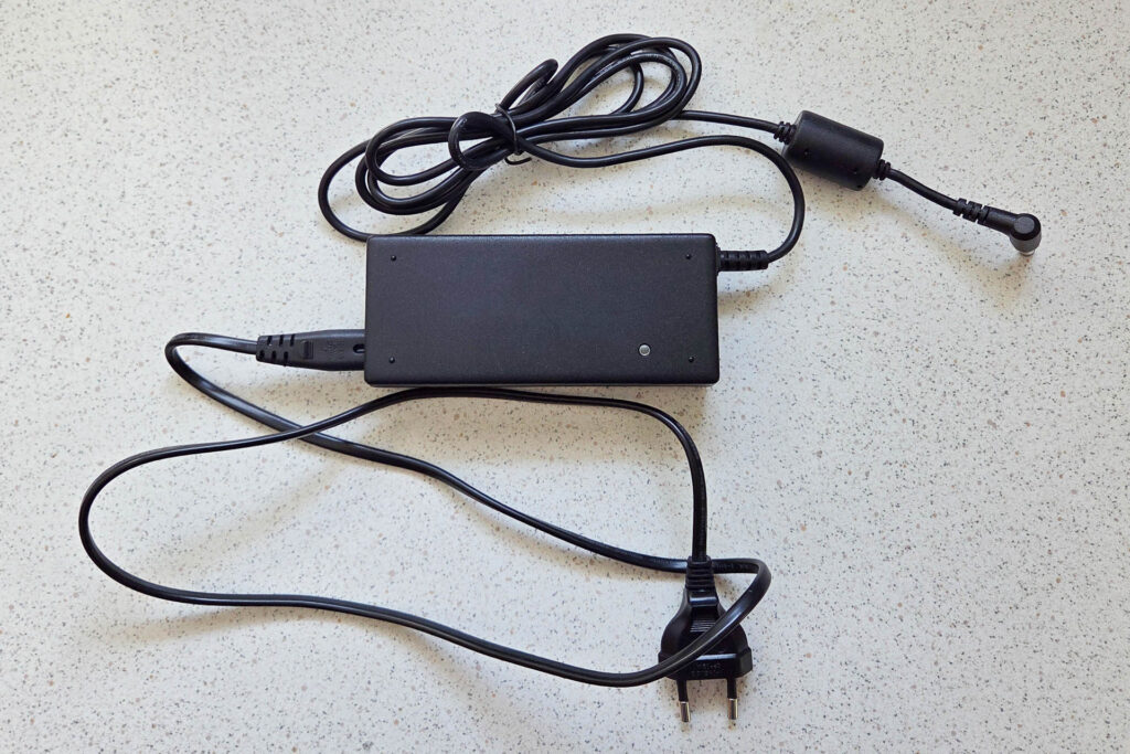
The battery board does not come with a charger. The board requires a charger that provides 5-24V DC with at least 1.5A via a 2.1×5.5mm DC coax jack (center positive). Instead of buying a new charger, I just got myself a discarded notebook charger for cheap. It is a 90W Fujitsu Lifebook charger that provides 20V at 4.5A.
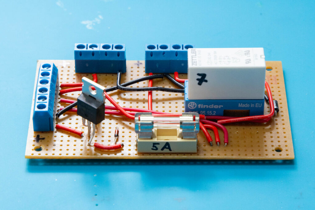
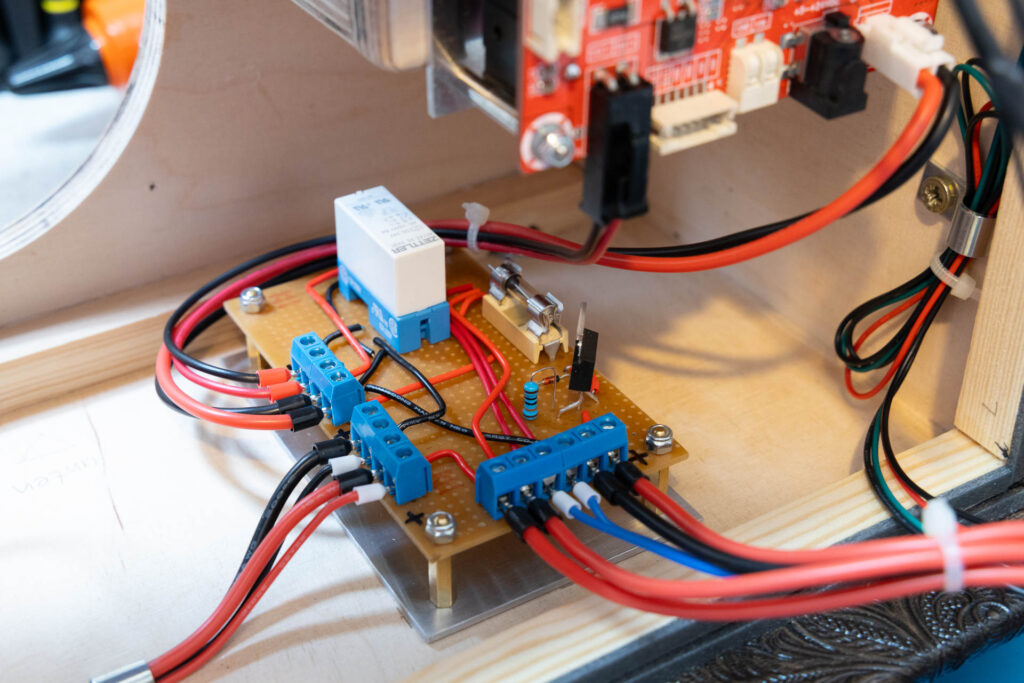
For some extra features, I created a small auxiliary board for the power supply. It provides the following functionalities:
- A 5A fuse to protect the input side of the battery board.
- A reverse polarity protection in case someone uses a charger with the wrong polarity.
- A charger voltage pass-through that powers the amplifier from the charger instead of the batteries in case the charger is plugged in. This provides enough power to the amplifier instantly to produce the maximum RMS of 2x20W+40W (even if the batteries are empty).
I installed this auxiliary board at the bottom of the cabinet, below the battery board. As for the other boards, I used a 2mm aluminum base plate for easier installation.
In the next post, I will describe how I designed and installed the control, input, and power supply panels.