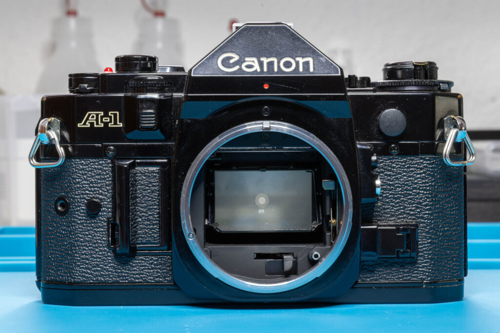
Disclaimer: The information I present in this post is based on the official service manual and renowned repair articles but mainly reflects my own experience. The description may be incomplete and might even contain errors. Consider that I am just a self-taught hobbyist, not a trained professional. Also, consider that any attempt to disassemble and repair a camera carries a certain risk to worsen its condition or to even breaking it completely.
The Canon A-1 contains some “mysterious” wires (called ‘SAVE adjust’) that may be connected to different soldering points in different copies of the camera. In this post, I’ll explain why that is and what you should consider when reparing the camera.
What’s This All About?
When you want to remove the mirror box of a Canon A-1, you have to desolder more than a dozen wires. Usually, these wires are connected to the same soldering points on all cameras. Except if they’re not. There are three wires (a green, a white, and an orange one) that may be connected to different soldering points on the AT (Aperture/Time) flexible board. There is no obvious pattern, especially none related to the production year of the camera. Therefore, they are not model variations. But what are they then?
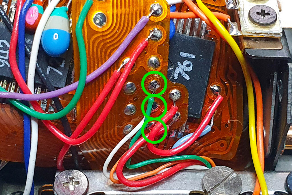
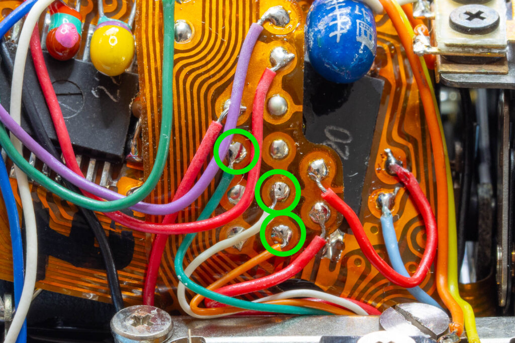
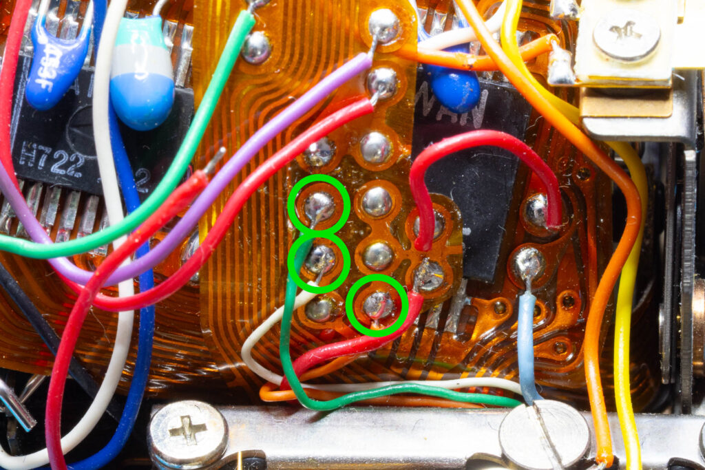
To understand the positioning of these wires, we first need to familiarize ourselves with a mechanism called ‘SAVE’.
What is SAVE?
In most exposure modes, the Canon A-1 measures the brightness of the scene with the aperture of the lens completely open. When you press the shutter release button, the camera closes the aperture down to the value set by the user or calculated by the CPU. To achieve this, the camera must always know the current aperture value while it is closing the aperture. Only then the camera can stop the aperture closing process when the desired aperture value is reached. According to the service manual, the complete aperture closing process will not take more than 30 msec.
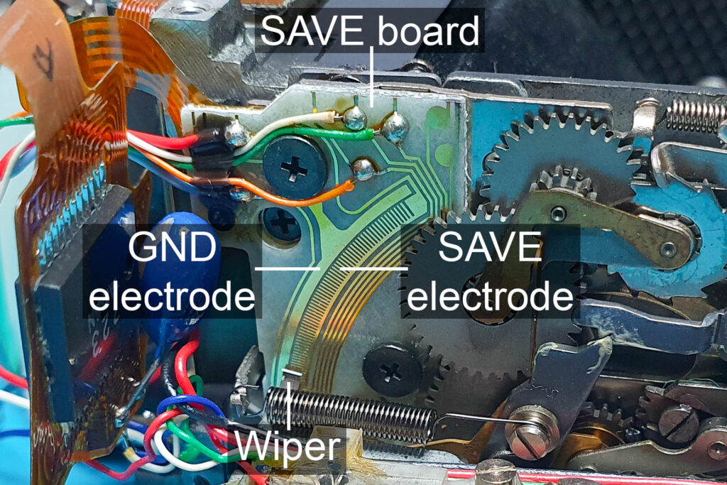
The current aperture value is transmitted from the mirror box (where the aperture closing mechanism sits) to the CPU via a red wire. The signal transmitted consists of a series of low-active pulses, each corresponding to 1/8 stop (EV). Since the CPU knows the maximum aperture of the lens (like f1.4), it can determine the current aperture value by adding 1/8 stop for each pulse. For example, for a f1.4 lens, 40 pulses (= 40 x 1/8 stop = 5 stops) represent an aperture of f8.0. In the Canon A-1, this signal is called SAVE (sometimes ‘S.AVE’), meaning “segmented aperture value electrode”. It is named after the way the pulses are generated: A circuit board attached to the mirror box contains a solid electrode (attached to GND) and a parallel, comb-shaped electrode (60+ teeth; attached to the red wire). A conductive wiper moves over these electrodes when the aperture is closing and the successive connects/disconnects of the electrodes produce the pulsed SAVE signal.
OK, but what are the green, white, and orange wire for?
The SAVE Adjustment
Somewhat simplified, the SAVE mechanism looks like this:

When the wiper is moved from the left side (resting position) to the right side during the aperture closing process, the following signals can be observed on the different wires:
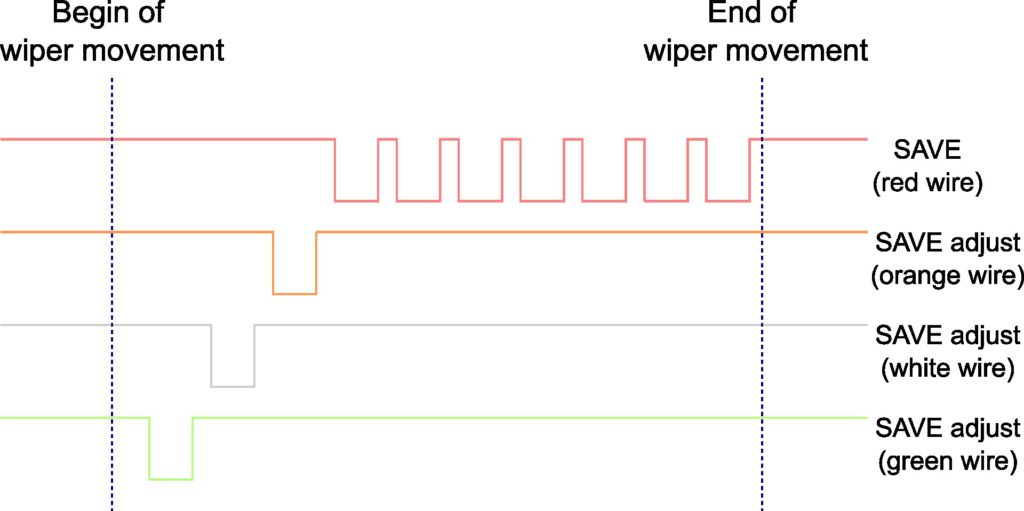
As can be seen, the three wires (green, white, orange) provide three additional pulses before the pulses on the SAVE wire start. These additional pulses can be used to adjust the SAVE mechanism regarding small deviations between the actual and the measured aperture value. By default, all three adjustment wires are short-circuited to the red SAVE wire. The resulting SAVE signal looks like this:
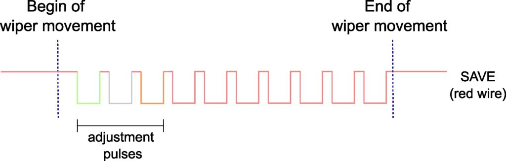
For adjustment of the SAVE signal, exposure measurements are performed with known EV, a well-calibrated lens, and a precise shutter speed. If these measurements indicate an overexposure, this can only be due to an overestimation of the aperture value by the camera. For example, the camera assumes that the lens was stopped down to f8.0 but the actual aperture value is only f7.4. The last pulse for the desired aperture value was generated too early by the SAVE mechanism while the aperture was not stopped down far enough. That is, the aperture closing process was stopped prematurely. In this situation one, two, or all three adjustment pulses can be removed by disconnecting the adjustment wires from the red SAVE wire. In this case, the SAVE mechanism starts to generate pulses after a longer movement of the wiper and the number of pulses representing the desired aperture value is only reached when the aperture was stopped down a little further. This will correct the overexposure.
This is how it looks like when the first two adjustment pulses are removed by disconnecting the green and white wire from the red SAVE wire:
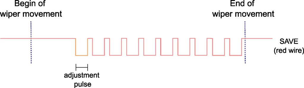
Each adjustment wire disconnected from the red SAVE wire (first green, then white, finally orange) will reduce the overexposure by about 1/8 stop.
Early copies of the Canon A-1 didn’t have the three SAVE adjust wires. Instead, the corresponding electrodes were connected to the SAVE electrode directly on the SAVE board. To disconnect the adjustment electrodes from the SAVE electrode, the connection had to be cut mechanically. I assume that this design was changed since it required the removal of the mirror box to adjust the aperture mechanism and the cutting of the connections was hard to undo.
Soldering Points on the AT Flexible Board
All three SAVE adjust wires (green, white, orange) are soldered to the AT flexible board. However, to which soldering points they are connected defines whether their additional pulses are added to the SAVE signal (default) or not. The relevant topology of the AT flexible board looks like this:
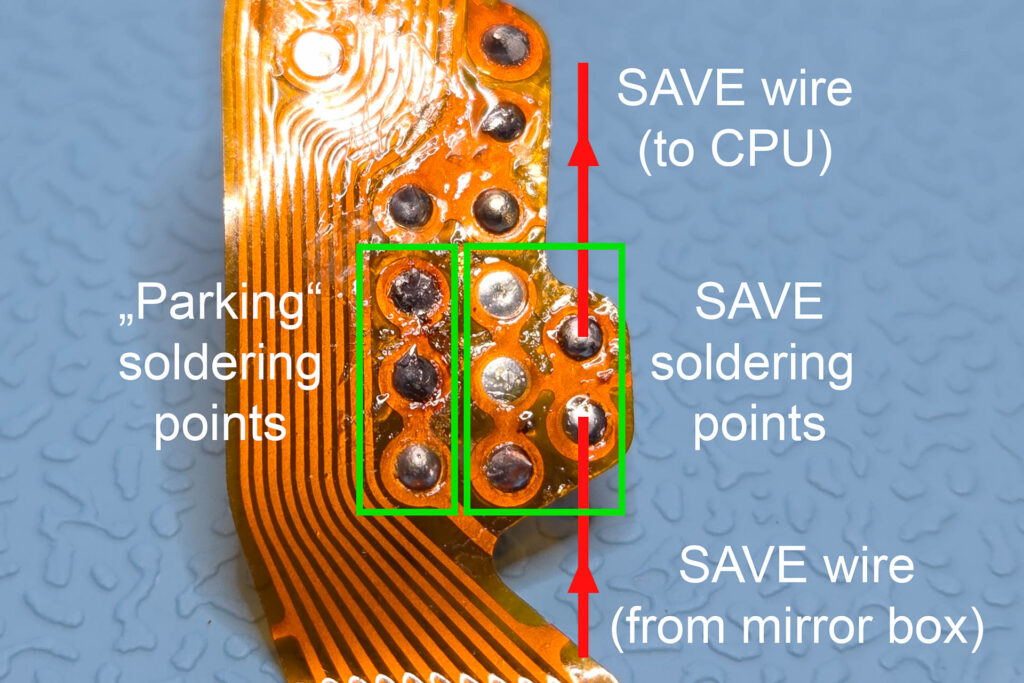
There are two groups of soldering points relevant for the SAVE signal. In each group, all soldering points are connected by traces on the board. The right group consists of five soldering points of which already two are occupied: one by the red SAVE wire coming from the mirror box, one by the red SAVE wire leading to the CPU. This group is responsible for combining the SAVE wire with the additional SAVE adjust wires. The left group consists of three soldering points. It is used as a “parking position” for all SAVE adjust wires that should not be combined with the SAVE wire. Based on the SAVE adjustment mechanism described above, four different assignments of SAVE adjust wires to solder groups are possible:
- Green, white, and orange wire are soldered to the SAVE group (= no SAVE adjustment).
- The green wire is soldered to the parking group, the white and orange wires are soldered to the SAVE group (= -1/8 stop).
- The green and white wires are soldered to the parking group, the orange wire is soldered to the SAVE group (= -2/8 stop).
- Green, white, and orange wire are soldered to the parking group (= -3/8 stop).
(In my repair practice, I have already seen version 1, 2, and 3, but not 4.)
What Does It Mean for You?
First, don’t be surprised if you see the SAVE adjust wires connected to different soldering points in different cameras.
Second, take a photo of the AT flexible board before you desolder the SAVE adjust wires. This ensures that you later resolder them to the correct soldering points. Don’t rely on photos you find on the internet; they might show a different variant than the one on your camera.
Third, don’t be worried too much if you can’t remember the soldering points of the SAVE adjust wires. The aperture adjustments made by these wires are not that big (1/8 stop per wire). Probably, there are other parts of your (already 40+ years old) camera, like metering or shutter speed, that have at least similar deviations from the ideal values. In this situation, I would suggest to just solder the green wire to the parking group and the white and orange wires to the SAVE group (version 2).
Fourth, if you really worry about 1/8 or 1/4 stop you can perform the adjustment procedure described in the service manual and resolder the wires according to the outcome of your measurements. However, I would only suggest to do this if you have a calibrated light source and a lens with an accurate aperture mechanism and have already adjusted the shutter speeds of the camera.
That’s all.