Disclaimer: In this post, I present a project that I finished successfully. However, it is not meant as a detailed construction manual. The description may be incomplete and might even contain errors. Feel free to use it as an inspiration for your own project but scrutinize the information presented here and use your common sense. Build at your own risk!
Nowadays, there are a lot of cheap 2.1 amplifier boards available, mostly based on two TPA3116D2 chips. Because I didn’t know better I just bought one of those for not more than 20€. To make a long story short: It just didn’t sound good and produced quite some noise. Furthermore, the only supported input sources were Line-In and Bluetooth and there was no way to control the amplifier remotely. As they say: You get what you pay for!

After some research, I finally bought a Up2Stream AMP2.1 amplifier board made by Arylic and the corresponding IR remote control for about 100€. It is also based on two TPA3116D2 chips but has a much better design (great sound, no noise). Beside this, it has five huge advantages over cheap 2.1 amplifier boards:
- It supports a multitude of input sources (Bluetooth, AirPlay, Line-In, SPDIF, USB, WiFi, Ethernet).
- It can be controlled via IR remote control and iOS/Android app. Also, an API for own control applications is available.
- It can act as an external sound card when connected to a PC via USB.
- Main functionalities can be accessed/controlled via JST breakout sockets on the board.
- It contains a DSP (Digital Signal Processor) that can be customized.

The amplifier provides two stereo fullrange channels and one mono subwoofer channel. By default, the crossover frequency is set to 110Hz (I changed it to 200Hz via DSP); no external filter is needed. The amplifier requires 12-24V DC. Depending on the voltage and current provided by the power supply and the impedance of the speakers, the amplifier can produce a maximum RMS of 2x50W + 100W (according to its datasheet). The power supply I use (will be described in a later post) can provide a maximum of 21V/5A. In this setup, the amplifier should produce up to 2x20W (stereo) + 40W (subwoofer).
The amplifier board is installed in the boombox in a way that no direct access is possible from the outside. This means, the following controls, LEDs, sensors, and sockets needed to be duplicated on the outside of the cabinet:
- The power/WPS button (also controls the pairing mode for Bluetooth and WiFi).
- The volume control.
- The Mode, Play/Pause, and Next Track button.
- The IR sensor.
- The LEDs that display the active input source.
- The Line-In and USB sockets.
The Ethernet and SPDIF sockets were not duplicated since they were not needed for my use case. The bass/treble controls were not duplicated since they can be set via remote control or smartphone app.
To connect the external controls, LEDs, and sensors to the amplifier board, I used its 9-pin breakout socket. This is a JST PH2.0 socket for which generic, pre-wired connectors are availabe.

The pinout of the breakout socket is as follows:
- Pin 1: +3.3V DC
- Pin 2: Ground
- Pin 3: Power/WPS
- Pin 4: LED for Line-In mode
- Pin 5: LED for USB mode
- Pin 6: LED for Bluetooth mode
- Pin 7: LED for WiFi mode
- Pin 8: ADC key (see below for explanation)
- Pin 9: IR sensor
The ADC (Analog-to-Digital Converter) key is used to transmit presses to several external buttons to the amplifier board using a single pin. This is done via a resistor ladder producing a unique input voltage for each of the buttons. I used the ADC key for the following buttons (only a subset of the supported ones):
- Power/WPS button
- Mode button (to switch between input sources)
- Play/Pause button
- Next Track button
I will describe the external buttons, LEDs, and sensors and where I placed them in a later post.
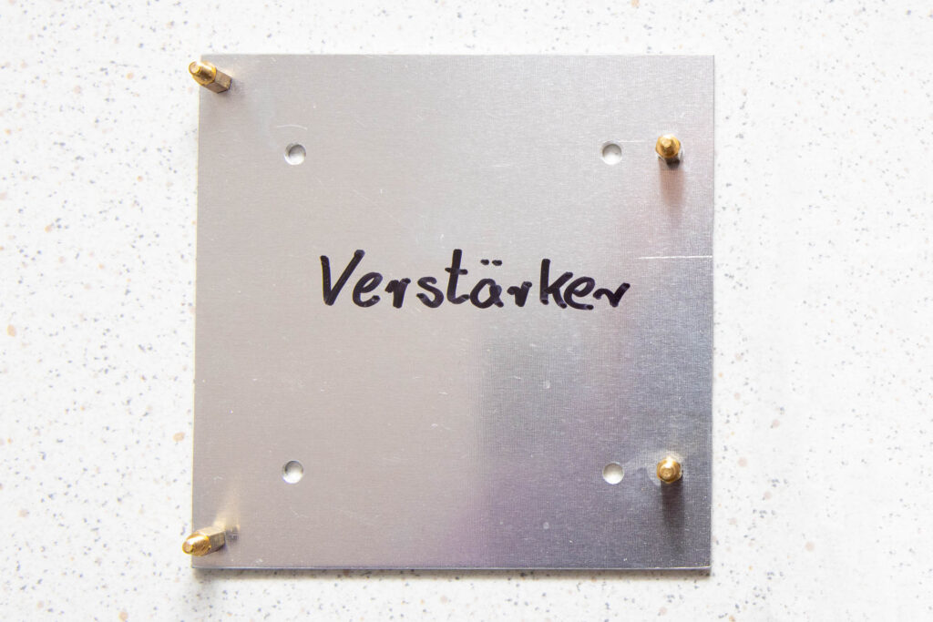
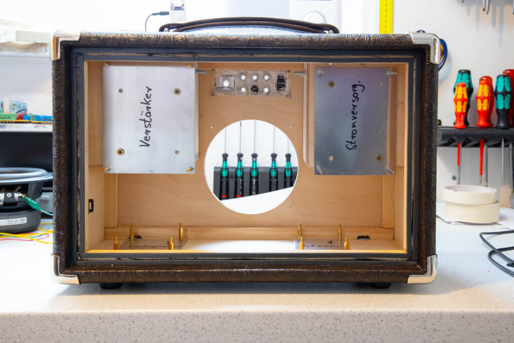
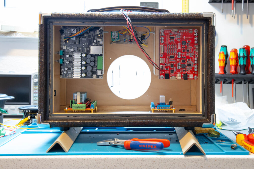
For easier installation of the amplifier board, I made a base plate out of 2mm aluminum. It has metal standoffs for the four mounting holes of the amplifier board. I screwed this base plate to the compartment of the right speaker (the left compartment when seen from the back). Then, I mounted the amplifier board to the base plate (with the knobs to the left) and screwed its WiFi antenna to the top of the cabinet.
In the next post, I will describe the power supply I used and how I installed it into the cabinet.